Highly efficient dc-dc converters extend battery run time on mobile autonomous robots
By TDK Lambda Americas, Technical Marketing
Automation / Robotics Electronics Power Supply / Management Engineering autonomous converters dc-dc Editor Pick power robotsIntroduction
We are frequently seeing articles about electric vehicles and one subject that appears frequently is how far can they travel between charges. The industrial sector is also very conscious of this aspect of battery powered equipment. Warehousing, inspection, disinfecting, security and many other applications are now utilizing robots.
These robots fall into two classifications: Automated guided vehicles (AGVs) are programmed to follow predetermined routes and if there is an obstruction, operation will be halted until the obstruction is removed is removed. Autonomous Mobile Robots (AMRs) utilize sensors or scanners and rely on mapping and data to find alternative routes to perform their function. A robot vacuum cleaner is a good example of this.
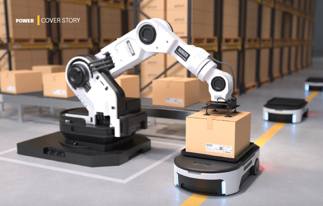
Highly efficient dc-dc converters extend battery run time on mobile autonomous robots. Source: Getty Images
Run time constraints
The run time of battery powered equipment is limited by two basic functions. One is the battery’s stored energy capability and the other is the amount of power drawn over a period of time. The run time could be increased by using a larger battery; however, this would increase the overall size and weight.
Run-time of battery powered designs is ultimately constrained by the law of conservation of energy. This essentially tells us that the amount of energy in an isolated system is fixed. Within such a system, energy can be converted from the battery to driving a motor for example. Between charging periods, there is a fixed energy budget that is established by the physical constraints of the battery itself, and it is incumbent upon the designer of the device to maximize the use of that budget.
Every battery powered device has one or more intended functions, jobs or tasks. These require energy to perform. The relationship between energy (E) power (P) and time (t) is given in equation . Be conscious of the amount of power drawn from the battery and the amount of time the battery is in use.
Optimizing the power conversion stage
36V or 48V batteries are being selected to reduce the weight and size of the copper wiring and to allow the use of more efficient dc motors. These voltages may not be compatible with controllers, wireless communication devices or sensors. Dc-dc regulators are then used to decrease the voltage to a useable level.
As most battery powered applications do not require galvanic isolation between the battery and other components in the robot, it allows non-isolated dc-dc converters to be deployed. These non-isolated converters are significantly more efficient than 95 to 96% efficient isolated converters and can be as high as 98.5%. This reduces waste heat, simplifies cooling, makes the converter smaller and they have a lower price. The non-isolated converters accept a wide DC input with a wide output adjustment range.
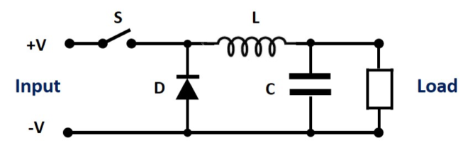
Fig 1: Buck converter simplified schematic. Source: TDK Lambda
Two types of non-isolated converters are commonly used. The “buck” converter which “steps-down” the input to a lower voltage (Figure 1) and the buck-boost converter which can step-up or step down the input voltage (Figure 2).
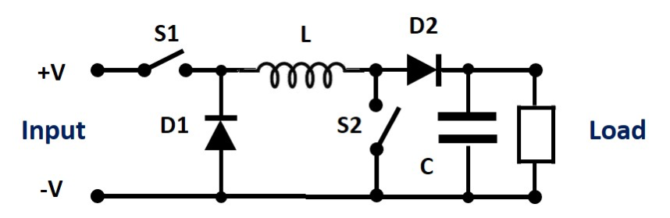
Fig 2: Buck-boost converter. Source: TDK Lambda
Note that a converter should incorporate a bulk capacitance across the input. The battery has source impedance and this can impact the dc-dc converter’s performance. Having low impedance energy storage at the input of the converter will help supply peak currents during stop and start load transients.
Conversion efficiency and quiescent consumption:
Even though the dc-dc converter has a high efficiency, there are some losses which can be reduced to maximize the battery life. It is necessary to select a converter that is correctly sized for the application and understanding the efficiency vs load characteristic will help achieve this. Figure 3 shows a typical efficiency vs load curve for the TDK-Lambda i7A buck converter which can provide up to 750W.
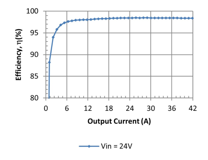
Fig 3: i7A dc-dc converter efficiency profile versus output current. Source: TDK Lambda
At light loading the efficiency of power converters can be quite inefficient. With less than 5% loading we can see that the efficiency drops from 98% to about 95%. This may appear a small amount of power, but care and diligence spent on every Watt loss of power will add up. Other dc-dc converters may exhibit a drop in efficiency at 10, 20 or even 30% loading.
Of course, the conversion efficiency will be 0% when a power converter is operated at 0% load. Even when the output load is zero, there will be some residual amount current drawn from the input. This is to keep the control circuits energized and maintain the output voltage which may otherwise gradually decrease over time due to parasitic impedances. This power draw under these zero load conditions is known as the quiescent consumption, a critical parameter in battery powered designs. If the robot performance requirements have been carefully determined, it is not uncommon for most sub-circuits to spend a majority of their time in a quiescent state, waiting to perform some task quickly and efficiently.
In some situations, some output voltages need not be maintained in low power sleep modes. In these cases, significant additional energy can be saved by inhibiting the supply rails to entire sub-circuits. Seeking a power converter with a logic level enable input (remote on/off function) can allow the system designer to turn quiescent sleep modes into deep sleep modes, capitalizing on a larger energy savings.
Some manufacturers support digital-to-analog control of the output voltage. This feature can be used to reduce the output voltage and slow down the motor when the robot is returning back to its charging station for example.
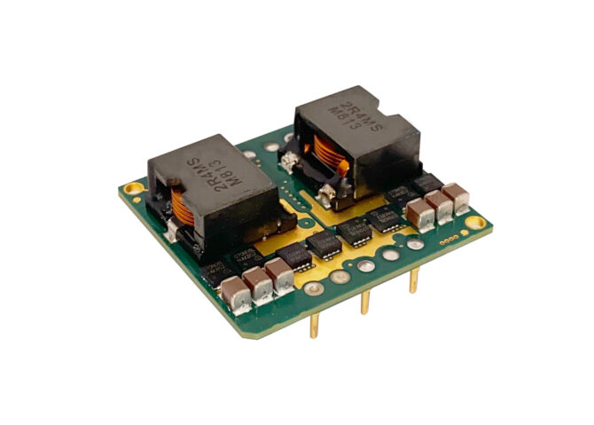
TDK-Lambda’s i7A 750W dc-dc converter. Source: TDK Lambda
Second order effects
Optimizing the power conversion design has several beneficial second order effects above and beyond the direct impacts highlighted thus far. By using a non-isolated converter, the requirement for a large, heavy ferrite transformer, which contributes to the size and weight of the end-device, is eliminated. In some instances, a non-isolated converter in a 1/16 brick package (34mm x 36.8mm x 11.5mm high) can offer the same amount of power as a 1/4 (58.4 x 22.9 x 8.8mm) or even a 1/2 brick (61 x 57.9 x 12.7mm) isolated converter. With lighter power electronics, the robot will weigh less reducing the motor power required to move the end device. This results in additional energy conservation and helps manage the energy budget mentioned earlier. Non-isolated converters can also have streamlined feedback loops, removing cost, complexity, and some quiescent load from the design.
Summary
The selection of a suitable battery for your next battery powered design is important. It is arguably just as important to optimize the efficiency of the devise’s electronics and power conversion stages, thus maximizing the lifetime of the battery. Special attention should be given to the choice of topology, ensuring that as much of the battery’s output voltage range is utilized as possible, including the conversion from the battery voltage to the associated electronics driving the motor and the associated control and navigation functions.
Consider partnering with an experienced power conversion company to address the needs of your next battery powered design. There are many standard products available and selecting the right product for the application is very important.