Accelerated lifetime study of 12-channel compact free space DWDM components
By Jan Watté, Cristina Lerma Arce, Mike Gurreri CommScope Connectivity - Belgium BV
Electronics Interconnect Engineering accelerated lifetime testing connectivity fiber optics passive optical devices Reliability statistical modeling wavelength division multiplexing WDMThe paper from which this article was generated was presented at the 2022 IWCS Cable & Connectivity Industry Forum, the premier technology event for the exchange of information about product, material and process innovation for cabling and connectivity solutions. Visit www.iwcs.org to learn about the next IWCS Forum.
———————————————
Overview
This article describes the accelerated lifetime testing that was carried out on 12-channel compact dense wavelength division multiplexing (CDWDM) devices and apply reliability modelling to predict their estimated lifetime. The components were optically monitored at various temperature and relative humidity conditions. By carrying out interval censoring and applying an Arrhenius-Peck model, the activation energy and humidity factor were determined, which allows us to calculate the failure rate under different field service conditions.
- Introduction
Network traffic has continued to surge at an unprecedented rate in recent years. With increased virtual work environments, video streaming services, online gaming, and growth in social media, this trend is expected to continue for the foreseeable future. The evolution of 5G and IoT also represents a fundamental change in the mobile ecosystem, where a combination of increased bandwidth, low latency, and improved power efficiency promises to drive billions of more connections. As fiber is pushed further to the edge, operators are challenged with cost-effectively reconfiguring their infrastructure to keep up with network demand.
Next-generation network topologies are now being deployed to deliver 10 Gbps, and accommodate future 25G and 50G speeds, which enables future waves of data growth. For instance, WDM PON creates a wavelength-based point-to-point architecture using a physical point-to-multipoint infrastructure [1]. This hardware-based traffic separation provides customers a secure and scalable wavelength link but enables the carrier to retain lower fiber counts, or in some cases utilize existing dark fiber, yielding lower operating costs.
WDM technology has long been a cornerstone of the network architecture for major multiservice operators (MSOs), with several device options commercially available [2]. One of these alternatives is compact dense WDM (CDWDM), which offer uniform losses that does not scale as the number of ports increase, giving an advantage over cascaded three-port WDM assemblies. In addition, the footprint is extremely compact, enabling CDWDM to be integrated into novel miniaturized network elements. Improvement of the assembly yields is expected to lower the cost per port. Therefore, free space CDWDM technology potentially can become an attractive alternative for state-of-the-art cascades of 3-port TFF devices when it shows a good long-term reliability [2].
Network downtime can have significant consequences considering the “always-on” expectation of today’s society and its reliance on technology. In most passive optical networks, silica-based planar lightwave circuits (PLC) have been widely employed as splitters in the outside plant. Their reliability and response to accelerated lifetime testing has been well-documented in literature [3]-[10]. In contrast to PLC splitters, the long-term reliability of CDWDM devices has not been fully assessed. To evaluate outside plant robustness, temperature and humidity acceleration factors have not been defined. Recently, a lifetime study of a 96-channel a-thermal AWG module, involving a novel temperature compensation packaging has been carried out, guaranteeing a 10-year service lifespan in outside plant conditions [11].
In this paper, we apply accelerated lifetime testing to 12-channel freespace CDWDM components and use it as a basis for predicting the estimated lifetime. The result of the study demonstrates that it is possible to reliably package these devices to assure long-term performance in outside plant environmental conditions.
- Free-space CDWDM Module
Free-space CDWDM technology uses free-space propagation of light that is repeatedly filtered by a series of TFFs (Thin Film Filter). These CDWDM modules are usually packaged in a metallic cartridge of reduced dimensions (typically 3-5 cm x 5-7 cm), in a butt-style configuration, where all ports are located at one single side of the module, and with a maximum number of ports around 12-16, corresponding to the different WDM channels.
The free space dense WDM modules that were used in this study are presented in Fig. 1.a. The optical devices consist of GRIN rod pigtailed fibers and a set of optical filters that are assembled in a predefined configuration on a metallic substrate (see Fig. 1.b). When needed, collimating optics is introduced in the free-space optical path to compensate for beam divergence that can affect the beam when the port count is high. The devices are pigtailed with ITU-T G.657 A1 fiber and the dimensions of the package are 7 mm x 29 mm x 49 mm.
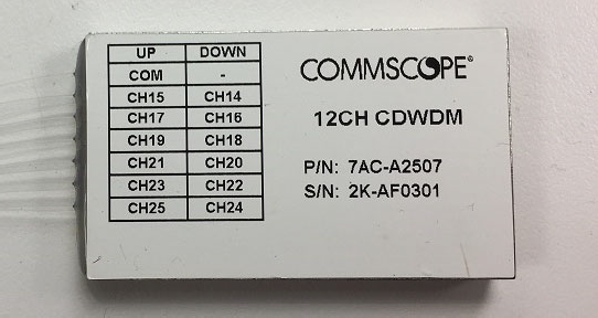
Figure 1.a. Packaged 12-channel CDWDM Device
Figure 1a
Optical signals carrying a set of multiple wavelengths are launched into the device through the common port and are directed to the first optical filter that subtracts the first wavelength. That signal passing the filter is propagating through the deflection prism at the rear of the device and is totally internally reflected when it is captured by the collimating lens of the drop port fiber.
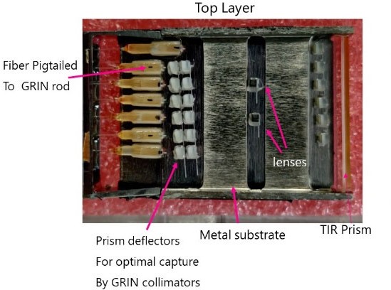
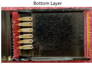
The reflected beam containing the remaining wavelengths propagates subsequently through the second filter, giving rise to the drop of the second wavelength. This process is iterated until all the wavelengths are demultiplexed. As a result, a smaller footprint is obtained than state-of-the-art WDM devices based on cascading three port filter WDM devices, which have been implemented widely in WDM networks so far.
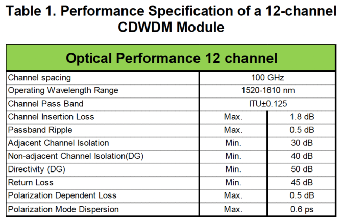
However, the footprint advantage puts more stringent demands on the outside plant robustness of the packaging, in particular for dense WDM components, which motivated this accelerated lifetime study. The optical performance specification of the 12-channel free space CDWDM devices is presented in Table 1.
- Accelerated Lifetime Testing
In total, 19 CDWDM modules with 12 channels were tested in a desktop sized highly accelerated stress test (HAST) chamber (see Fig. 2).
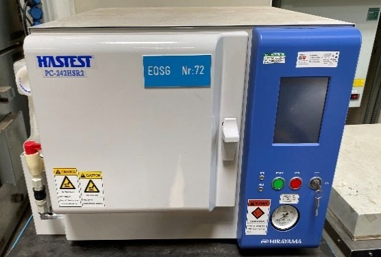
Figure 2. HAST chamber used to age the CDWDM devices.
The modules were put on a storage basket and measured with a swept-wavelength measurement photonic application suite with fast IL/PDL application, at discrete time intervals allowing for interval censoring. As can be noted from Table 2, four different accelerated lifetime testing (ALT) runs were executed, representing four different combinations of temperature and relative humidity conditions.
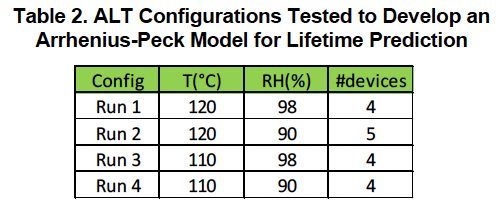
The typical sample size per run was four. A representative spectral loss measurement acquired by the test equipment of one CDWDM component in the ALT runs is shown in Fig. 3.
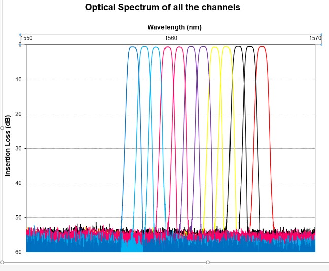
Figure 3. Spectral Loss Measurement of a CDWDM 12-
channel Component
- Optical Performance of CDWDM Devices
The CDWDM devices subjected to the harsh environmental conditions were measured at discrete time intervals with the swept wavelength system setup to monitor the drift in insertion loss as a function of aging time. The fact that we cannot measure in-situ in the HAST climatic chamber forces us to exploit interval censoring. For the most aggressive ALT conditions from Table 2, interval times were taken smaller than for the other conditions where the time-to failure can be much longer. The time-to-failure is recorded as the time that is required for one of the 12 ports to yield a change in attenuation that is greater than 0.5 dB. Fig. 4 shows a graph of the excursion loss behavior for the different ports of a sample that was monitored at a temperature of T=120°C and a relative humidity of 98%. The port ITU-25 was observed to fail in the interval 175-245 hours.
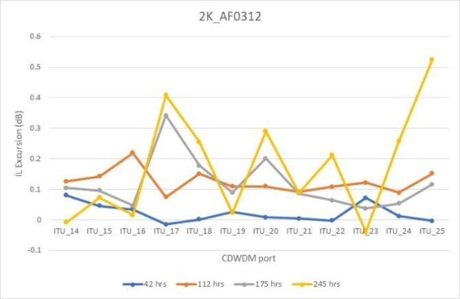
Figure 4. Excursion Loss Behavior of a CDWDM Component Tested at T=120°C, RH=90% and Measured with a Swept Wavelength System.
Table 3 shows the time-to-failure data obtained by interval censoring (12) for all the CDWDM devices that were measured in the four configurations outlined in Table 2.
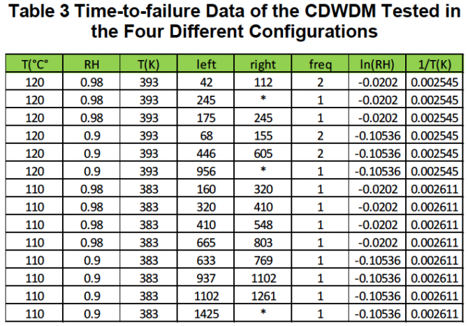
Note: Failures occurred between time data from column left and column right. The frequency gives the number of tested devices from that batch, which failed in the corresponding time interval. The devices where failure was not observed are noted with an in the right censoring column.
Commercial statistical software, Minitab 19, was used to evaluate the failure data and build an ALT model. A common Weibull slope for the failure data pertaining to the different stress conditions was assessed by a maximum likelihood estimation (MLE) algorithm (see Fig. 5). For the disclosed Weibull slope, a design rule was derived for the model’s Weibull scale parameter.
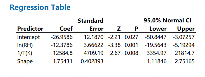
To this purpose, a closed form was used comprising an Arrhenius term and a power term for the relative humidity, coined as an Arrhenius-Peck law. As such the ALT model is characterized by an activation energy Ea=0.969 eV derived from Ea/kB=12584 with kB=8.617*10-5 eV/K (see Table 4). The MLE fitting yields a humidity factor of -12.3786. These two parameters from the Arrhenius-Peck model 12 allow us to predict the estimated ppm (parts per million) failure rate after 20 years of field service when the CDWDM devices are incorporated in typical network elements.
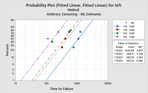
Figure 5. Weibull Plots of CDWDM Failures Recorded during the ALT Testing
Table 4. Arrhenius-Peck Regression Model Derived
from Minitab
- Evaluation of Device Failures and Lifetime Prediction
The ppm failure rate can be calculated for a temperature, T and relative humidity, RH, condition according to the following relationships, which incorporate the regression coefficients from
Table 4.
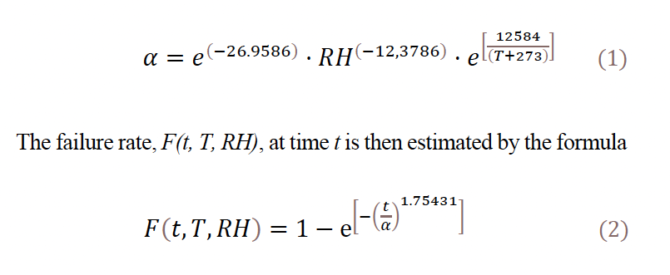
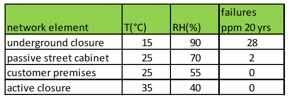
Table 5 shows the calculated ppm failure rate for underground closures, passive street cabinets, customer premises elements and active closures. Temperature and relative humidity conditions representative for a lifespan of 20 years were taken from (13, 14).
Table 5. Calculated ppm Failures for CDWDM Devices
Installed in Different Network Elements
The sealing glue at the edge of the device, where the optical fibers leave the package, is discolored after prolonged testing (see Fig. 6.a). In an attempt to find the root cause of the device failures, most could be traced back to delamination of the acrylate fiber coating inside the package (see Fig. 6.b). It is unclear whether epoxy that spilled onto the fiber coating can account for the observed insertion loss drifts.
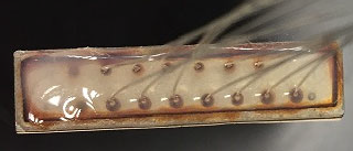
Figure 6.a. Picture of the Output Ports Embedded in a Sealing Adhesive after Prolonged ALT Testing.
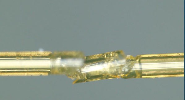
Figure 6.b. The predominant failure mode is the delamination of the fiber coating inside packaging.
- Conclusions
An accelerated lifetime study has been executed to assess the long term outside plant robustness on CDWDM devices to estimate the implementation risk of this kind of WDM components in different types of network elements. The outcome of this study complements the environmental testing that has already been performed on the latter components. In addition to temperature cycling and water immersion tests, 2,000 hours damp heat testing (85°C, 85 % RH) has also been performed, yielding that all samples passed the testing. The ALT study provides convincing additional data, which demonstrates that the risk of implementation of free space CDWDM devices, as a smaller footprint alternative to state-of-the-art cascades of 3 port filter WDM’s is low. The worst-case failure rates over a lifetime of 20 years were found to be smaller than 50 ppm and comparable to those of PLC splitters.
As mentioned previously, the smaller footprint alleviates the need for overlength storage and can pave the way for smaller network elements. This will be an asset for WDM integration in terminals where the reduction of the footprint is also triggered by smaller form factor ruggedized connectors.
—————————
The Authors

Jan Watté earned his PhD in Applied Physics from the KU Leuven in 1993. He joined Raychem in 1998 as a fiber optic test engineer. The company became acquired by TE Connectivity in 2001 and later in 2015 by Commscope. He was involved in development programs of passive optical devices and fiber optic connectivity systems. In addition, he has a track record of having led numerous applied research programs financially supported by VLAIO Flanders and by the EU. In 2017 he was appointed Engineering Fellow.

Cristina Lerma Arce received her M.Sc. degree in
Telecommunications Engineering from the Polytechnic University
of Valencia (UPV), Spain, in 2009 and her Ph.D. in Photonics from
Ghent University, Belgium, in 2014. Since then, she joined TE
Connectivity, later acquired by Commscope, where she has been
working as product development engineer in the Optics Group of
the Network Connectivity segment, focusing on passive and electrooptical fiber optic devices. She also has led several photonics
research projects in collaboration with different research institutes
in Europe.

Michael Gurreri received his B.S. degree in Mechanical
Engineering in 1997 and his M.S. in Engineering Science in 2005
from Pennsylvania State University. He joined CommScope (via
divestiture from TE Connectivity and prior AMP) in 1998 as a
Product Development Engineer in the Fiber Optics Business Unit,
taking on various management and technology development roles
throughout his career. Mike leads a team of distinguished optical
engineers in the Network Connectivity segment of CommScope and
is a US delegate to IEC SC 86B, where he received the 1906 award
for contributions to multifiber optical interfaces. He holds over 50 US patents in the field of fiber optics and was named a CommScope
Master Inventor in 2020.
In Addition
The authors are indebted to Ann Vanderstukken and Walter Mattheus for carrying out the optical measurements. The technical support of Luc Verbinnen for the HAST equipment is gratefully acknowledged. In addition, we would like to thank Michael Maris and Peter Merlo for supporting this research.
————————
- References
[1] ITU-T G.9802.1, “Wavelength division multiplexed passive
optical networks (WDM PON): General requirements”, 8/2021
[2] Watté, J., Cristina Lerma Arce, C., Panapakkam, V., “Nextgeneration
WDM technologies offer choices to meet rising
bandwidth demands”, CommScope whitepaper, 2021
[3] Yamada, Y., F. Hanawa, T. Kitoh, N. Takato, and T. Maruno.
“Reliability of silica-based planar-lightwave circuit-type 1Å~ 8
splitter module”, Optical Fiber Communication Conference, p.
WH3. Optical Society of America, 1993.
[4] Hibino, Y., F. Hanawa, N. Takato, H. Nakagome, Y. Inoue, T.
Miya, and M. Yamaguchi. “Silica-based PLC splitters which
satisfy reliability requirements for more than 5000 hours”,
Optical Fiber Communication Conference, p. PD7. Optica
Publishing Group, 1994.
[5] Hibino, Y., Hanawa, F., Nakagome, H., Ishii, M. and Takato,
N., “High Reliability Optical Splitters Composed of Silica-
Based Planar Lightwave Circuits”, Journal of Lightwave
Technology, Volume 12, Issue 8, 1995, pp.1728-1735.
[6] Aratake, A., “Field reliability of silica-based PLC splitter for
FTTH”, Optical Fiber Communication Conference, pp. Th4H-
- Optica Publishing Group, 2015.
[7] Aratake, A., “High reliability of silica-based 1Å~ 8 optical splitter
modules for outside plant”, Journal of Lightwave Technology,
Volume 34, Issue 2, pp.227-232, 2016.
[8] Zheng, Y., Yao, W., Bingxing X., Lianqiong, J., “Online
Reliability of Planar Lightwave Circuit Splitters” CLEO:
Science and Innovations, Optical Society of America, pp.
JTu2G-15, 2020.
[9] GR-1221-CORE, “Generic Reliability Assurance Requirements
for Passive Optical Components”, Telcordia, Issue 3, 2010
[10] IEC 62005-2:2001, “Reliability of fibre optic interconnecting
devices and passive components – Part 2: Quantitative
assessment of reliability based on accelerated ageing test –
Temperature and humidity; steady state”
[11] K.-S. Yun, C.-H. Yu, K.-S. Lin, Y.-S. Kim and I. Jeon, ‘High
reliability evaluation and life time prediction of 50 GHz
athermal module, Appl. Sci 2021, 11, 11107, 2021
[12] W.B. Nelson, ‘Accelerated testing, statistical models, test plans
and data analysis, Wiley (2004)
[13] ETSI EN 300 019-1-8, “Environmental Engineering (EE):
Environmental conditions and tests for telecommunications
equipment, Part 1-8: Classification of environmental conditions;
Stationary use at underground locations, V2.1.4, 2003-04
[14] ETSI EN 300 019-1-3, “Environmental Engineering (EE):
Environmental conditions and environmental tests for
telecommunications equipment, Part 1-3: Classification of
environmental conditions, Stationary use at weather protected
locations”, V2.4.1, 2014-04
failures
network element T(°C) RH(%) ppm 20 yrs
underground closure 15 90 28
passive street cabinet 25 70 2
customer premises 25 55 0
active closure 35 40 0
- Pictures of Authors
Jan Watté
Michael Gurreri
Cristina Lerma Arce