Integrating and testing ZigBee modules
By Chris Loberg, senior technical marketing manager, Tektronix Inc.
Wireless Engineering IoTMost Internet of Things projects are likely to involve some sort of wireless connectivity, typically Wi-Fi, Bluetooth or ZigBee. Despite its relatively low performance, ZigBee’s very low power consumption makes it well-suited for many IoT applications.
While IoT is the buzzword du jour, when you come down to it most IoT projects are essentially the latest take on wireless-enabled embedded systems. This means that embedded system designers are more in demand than ever, and even engineers without an extensive RF background are being asked to troubleshoot designs that involve wireless technologies such as ZigBee.
But just as embedded systems are changing, so too is test instrumentation, most notably with the advent of oscilloscopes with a built-in spectrum analyzer. This offers significant advantages for designers since they can use an oscilloscope – the center instrument on most design benches – to efficiently test and debug their designs from end-to-end.
This article first looks at how ZigBee stacks up compared to other alternatives for IoT applications and then outlines techniques for evaluating and testing ZigBee modules to assure good communications in ZigBee-based designs using a mixed domain oscilloscope.
Adding RF to IoT designs
There are numerous wireless technologies and standards available today, but three stand out from the pack for embedded and IoT applications: ZigBee, Bluetooth, and Wi-Fi.
The use of these technologies has been growing rapidly over the past few years with no end in sight. The Wi-Fi Alliance claims there are more than 4 billion Wi-Fi enabled devices ready to connect today. ZigBee is in the process of emerging from a group of incompatible or proprietary technologies to become the de facto worldwide standard for the smart home, and is expected to see broad adoption in the coming years.
With all of the different wireless standards available to choose from today it can become a challenge just to figure out which will work best for your embedded or IoT project design. Table 1 provides a comparison of these three wireless standards and their typical applications.
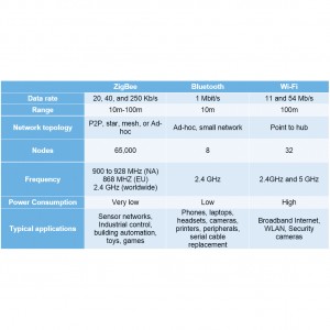
Table 1: Comparison of popular RF technologies.
ZigBee, Bluetooth, and Wi-Fi each have their own strengths and weaknesses that can be used to evaluate which would be best-suited for a particular application or design. The standard with the highest data rate capabilities is Wi-Fi at up to 54 Mb/s. This makes Wi-Fi the optimal solution where high data throughput is important, for example streaming video or sharing files. The main downside to Wi-Fi is its large power consumption, a problem for IoT devices that run at very low power to extend battery life. Also Wi-Fi is limited to point-to-hub connections, meaning devices cannot freely communicate with one another without first connecting to a central hub.
Bluetooth is in the middle compared to Wi-Fi and ZigBee when it comes to performance. It is low power and is able to connect to multiple devices directly without the need for a central node. This makes Bluetooth a great candidate for the use in peripheral devices such as wireless keyboards, mice, and headsets. Bluetooth is limited in range so it is best used when all the devices being connected are in the same room.
ZigBee is the lowest performance of the three standards, but can often be the ideal choice for IoT applications. A key factor is that ZigBee uses very low power compared to the other two. Where Wi-Fi and Bluetooth battery life might be measured in hours or days, ZigBee can be optimized to last for weeks or months. Another impressive feature is ZigBee’s ability to have up to 65,000 devices connected to one another in a mesh type network.
With most IoT projects turning to ZigBee, it is important that designers know how to test their devices properly. There are a few different form factors to consider when looking for a ZigBee module to add to your device. For example, there is the radio-only IC that is the barebones of the wireless technology and provides the greatest flexibility in your designs. However you must provide all the amplifiers and microcontrollers needed to utilize a ZigBee IC. Next there is the radio module with microcontroller and amplifier already integrated. This setup is the easiest to use as all the components necessary to make the wireless connection possible are already configured and assembled. The downside is that this form factor is larger and less customizable.
A mixed domain oscilloscope (MDO) is ideal for testing ZigBee and other embedded wireless technologies because of its unique ability to analyze signals in both the time domain and frequency domain. Although you can use an MDO as a mixed signal oscilloscope or as a spectrum analyzer, the real power comes from the integration of the two. For example, it provides the ability see how a ZigBee design performs in both the time and frequency domains on a single instrument. Trigger, search and analysis tools are useful for such tasks as identifying analog and digital anomalies, decode of serial buses alongside waveforms, and viewing the RF spectrum at any point in time.
Once the approach to the radio implementation is selected, the appropriate printed circuit board lay out, and any necessary software written, there are a number of tests to be performed to ensure good communication in a ZigBee-based design. For many applications, there will be serial communications between the radio system and other parts of the product. For example, the microcontroller IC and modules use a four wire SPI connection to control the radio IC and any related components such as a power amplifier.
Testing radio operation
To illustrate some of the tests that should be carried out to verify radio operation, an amplified radio module with a demonstration board was used. The screen shots were taken using a Tektronix MDO4000B series mixed domain oscilloscope which allows simultaneous time correlated viewing of RF, analog, and digital signals. Setup and data commands are sent from a PC to allow manual control. Figure 1 shows the test setup. Note that a direct connection to the radio is used to facilitate power and other measurements. A calibrated antenna could equally have been used to take the RF measurements.

Figure 1: Test connections between microcontroller, demo board, ZigBee module, and an MDO4000B series mixed domain oscilloscope.
ZigBee RF compliance testing
As shown in Figure 2, an MDO allows simultaneous viewing of the radio spectrum and the power supply. The channel spacing for ZigBee is 5MHz. The 20 dB channel bandwidth should be significantly less than the channel spacing. The measured occupied bandwidth of 2.3MHz shown in Figure 2 is well within the specification. The output power is expected to be in the range of 20dBm. The screen shows the output spectrum in the lower part of the screen and direct measurements of bandwidth and power. The test cable drop is about 2dB in this frequency range, so the power measurement is in the range of what is expected. The orange bar at the bottom of the top half of the screen indicates the time period in which the spectrum trace is displayed.
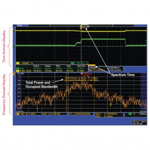
Figure 2: Time domain and frequency domain displays. The orange bar represents the spectrum time of the frequency domain display relative to the time domain measurements.
The spectrum time is defined as the window shaping factor divided by the resolution bandwidth (RBW). In this example, using the default Kaiser FFT function (shaping factor 2.23) and the RBW of 11kHz, the spectrum time is approximately 200us. Moving the spectrum bar across the time domain window allows the spectrum and measurements to be taken at any time during the packet transmission. This acquisition correlates just after turn-on of a radio packet transmission.
Simulated power supply failure
In Figure 3, a 1.5 ohm resistor is placed in series with the module to simulate the effect of a depleted battery. The current drawn by the module is only a few milliamps lower, but the voltage drop is about 230 millivolts. Note that the output power is reduced by 1dB as measured by the RF power measurement and there is a slight increase in the adjacent channel noise can be seen in the spectrum display.
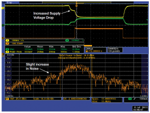
Figure 3. Spectrum and measurements with resistance in series with the module power source to study low power performance behavior.
The lower output can also be seen on the amplitude versus time (Trace A). It is often necessary to understand the performance of radio transmitters during low battery conditions or conditions when the power supply becomes current limited to understand the margins of radio compliant performance.
Digital Commands
Radio ICs and modules need to be set up to meet the operating requirements of the specific application and any protocol specific setups. The MDO allows decode of the SPI commands to the ZigBee module. This architecture supports simplified measurements between SPI command triggering and correlated RF events. In Figure 4, the trigger event is now the SPI command, the radio Transmit trigger command. Markers on the Time Domain display show the SPI command to current draw (at the beginning of the RF Tx turn-on) is 1.768ms.
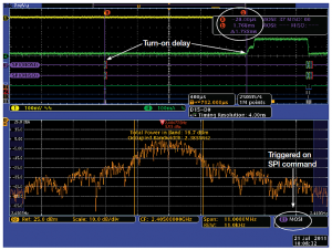
Figure 4 Subsequent acquisition triggered on SPI command shows delay between command and radio turn-on.
This allows you to quickly determine the delay between when the command is given to the ZigBee device and when the ZigBee begins to transmit.
Summary
When it comes to developing an Internet of Things product or device, some sort of wireless capability is must. For many of the latest IoT projects, designers are turning to ZigBee as the wireless technology of choice for its low power consumption and ability to join vast mesh networks.
With the explosion of wireless in embedded and IoT designs comes the need for new tools to test and troubleshoot these designs. One such tool is the mixed-domain oscilloscope that provides the ability see how a ZigBee design performs in both the time and frequency domains on a single instrument.
About the author
Chris Loberg is a senior technical marketing manager at Tektronix responsible for oscilloscopes in the Americas Region. Chris has held various positions with Tektronix during his more than 13 years with the company, including Marketing Manager for Tektronix’ Optical Business Unit. His extensive background in technology marketing includes positions with Grass Valley Group and IBM. He earned an MBA in marketing from San Jose State University.