Solving water damage to electronics
By Aculon Inc.
Electronics Production / Materials Engineering circuitry circuitry electronics protection protection water-proofing water-proofingHere are some new ways to solve this multi-billion dollar issue facing electronic designers
The miniaturization of electronic products continues to drive printed circuit board (pcb) manufacturing towards smaller and more densely packed boards with increased electronic capabilities. With virtually every electronic device containing at least one pcb, they are a modern marvel and one of the most disruptive innovations of the last one hundred years. However, they have an Achilles heel…..water!
Introduction
Pcbs consist of fiberglass-reinforced, copper-clad epoxy laminate onto which the ‘wiring’ for circuits are formed by selectively etching away copper to form individual traces on the board. After printing a pattern of solder pate, the individual electronic components are then placed then bonded to the interconnecting circuits by melting the solder paste in a high temperature oven. Since the copper tracks are immobilized in/on the board, and very careful attention and control is part of the assembly process, there are minimal chances of short circuits – except when in contact with water.
Whether submersion, a splash or even fog, printed circuit boards are particularly sensitive to liquid exposure. In the smartphone industry alone, liquid damage is a huge issue. According to research from IDC (International Data Corp.), more than 900,00 smartphones are damaged by liquids every day globally. IDC’s research revealed that liquid damage is the second-largest cause of damaged smartphones (the primary source of damage being broken screens) with the impact estimated to be worth nearly $100 billion each year. IDC claims that by 2020, more than 1.7 billion smartphones will be shipped at a market value of $398 billion, with the problem of liquid damage only becoming more widespread if it is not addressed.
However, the need for waterproofing PCBs goes way beyond smartphones. There has been tremendous interest from producers of tablets, IoT devices, appliances and even automated component manufacturers. Because of their delicate nature, electronics manufacturers are challenged to find reliable, economical and high-performance materials that minimizes or mitigates the damage that compromises safety and operation of electronic devices. Increasingly, designers want to build fluid protection into the design to improve product reliability and reduce device failures. As a result of claims by several leading mobile phone brands, consumers are now looking for water resistance and protection as a feature of new and improved devices.
Brief history of conformal coatings
Unsealed electronics are also problematic when exposed to dust. When left unpowered in a humid environment, dust absorbs moisture from the air, which can cause corrosion. Over time, this will cause electrochemical reactions with the various metals on a pcb and conductive dendritic traces can short-circuit the device. Protecting pcbs from this kind of damage in high-risk components (automotive, aerospace, etc.) has been the job of conformal coatings (either liquid-based polymer chemistry or vacuum-based parylene), which create a physical barrier between dust and circuitry.
However, conformal coatings have not been capable of protecting pcbs from direct exposure to liquid water until very recently; that has only been possible previously by full physical gasketing of the device. While physical gaskets are the method of choice for most manufacturers, they are expensive and complex to use in large devices (i.e. bigger than a watch), and are prone to failure when they experience thermal cycling.
Water-resistant epoxies are available in the market but they are not specifically used for pcbs. Although they possess excellent chemical and abrasion resistance, they can cause stress on components during thermal cycling and often crack when they are used over large areas. Due to fluctuating temperatures during the application process it can cause considerable drift in viscosities and difficulties in controlling cure times and inconsistencies in coating thicknesses.
Liquid electrical tape is yet another method. It uses a rubber coating that is designed to provide electrical insulation for electronic devices, which is applied over connectors and solder. However, liquid electrical tape makes minimal bond with most surfaces, rather it bonds to itself to surround an item. Eventually, water or dust can creep in especially along wire connections.
These processes are tedious, complex and can be expensive, and more importantly they are not effective in protecting the critical components of electronic equipment from direct exposure to liquid water (they were not designed for this) Consumers have had to rely on specialty cases to protect their devices, which take away from the integrity and functionality of the design.
Current Developments
In the ever-evolving pcb market, a ‘no mask’ category of surface treatments has emerged due to some recent discoveries made in research and development in the chemistry of conformal coatings These surface treatments are capable of forming a ‘true’ conformal coating that does not have significant differences in thickness across complex parts which allows for much greater water resistance when compared with traditional conformal coatings. Additionally, while previous chemistries required masking of connector hubs so that other parts could be electrically connected after coating, these new surface treatments can be applied directly onto connectors which now prevents these points from becoming the point of failure upon water immersion. These hydrophobic coatings are economical and can be applied inline via straightforward processes at the manufacturer. They also eliminate the need for costly capital investments and mitigate the bottlenecking batch process of vacuum-based manufacturing or masking operations.
Water Resistance Testing Standards
The IPX standard rating provides a clearer picture of how water resistant a component is compared to vague marketing terms such as ‘water-resistant’. The IPX rating system is generally used to categorize the level of water resistance an assembled device can achieve; this testing ranges from IPX0 (not water-resistant) to IPX8 (full water immersion to a depth and time specified by the manufacturer). IPX testing requires that full device builds are used, in some cases this is not possible due to the cost or that it may be early in the development cycle of a new device. As an alternative, standardized test boards have been historically used to compare different coatings.
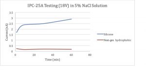
Coatings are first applied to standardized test patterns (IPC-25A test boards, D pattern) according to the coatings manufacturers’ instructions. The circuit boards are then connected to an external power supply and maintained at a constant voltage while using a digital ammeter to measure current across the electrodes. The measured current flow at a specific voltage (voltage chosen is defined by the manufacturer) is measured and coatings are compared.
Modifications to Standardized Testing
While IPX testing does not specify the kind of water used for testing live devices, using the IPC-25A boards in tap water can be problematic as the measured current density tends to fluctuate widely as the resistance of tap water varies widely and complex electrochemical reactions happen (e.g. formation of a copper oxide ‘skin’ over the electrode causing the measured current to drop) that can create insulating states on the electrode surfaces. For these reasons, we use salt water solutions so that any formed oxides are dissolved more quickly and that the resistance of the water does not dominate the circuit.
In order to measure the ability of a coating to physically deform under the pressure of a push-pin connector (‘push-through connectivity’), a four-point probe connected to gold-plated probes ‘pogo pins’ is used to measure the resistance of the coating on tin substrates. If the resistance of the coated tin panel is not significantly different (typically in the milliohm range) via this measurement method than an uncoated tin panel then the coating is considered as having push-through connectivity.
As previously mentioned, the difficulty with running water resistance testing on full device builds has necessitated the use of standardized rest boards. However, this reliance on using flat substrates does not adequately represent real PCBs that have complex topologies where current may be flowing in many different areas (not just on the flat board surface). This can cause false positives when the results from IPC-25A board level testing are translated into live device tests. As an additional test we run live device testing with a simple pcb (a surface-mounted light emitting diode/power source/resistor combination) to monitor whether shorting occurs while powered up while submersed in salt water. Observation with an optical microscope verifies whether any damage (oxidation, corrosion, coating spalling, etc.) has occurred as well; this can indicate how well different coatings can achieve true conformal coating over complex surfaces. This test combined with the results of the aforementioned two can help device manufacturers make decisions on narrowing the field before engaging in full device testing.
Results and Discussion
In this section, two coatings were chosen to demonstrate the differences between traditional conformal coatings and newly-developed conformal coating chemistry. The incumbent was a 1-part high solids silicone conformal coating which has a dry film thickness of approximately 100 microns, whereas the next-generation conformal coating was a hydrophobic polymer coating with a dry film thickness of approximately 35 microns.
For immersion testing in salt water with IPC-25A standard test boards (D pattern), a Keithley 6487 Picoammeter was used to deliver 18V source voltage while current was measured. Both coatings performed well as no significant current was measured at 18V (an uncoated board would be showing currents >10 milliamps in this test). 
For push-through connectivity testing, both coatings were applied to tin substrates and their resistivity measured with four gold-plated ‘pogo pins’ (pins depressed halfway through their travel distance) connected to a 4-point probe micro ohmmeter (HP 34420A). The control substrate had a resistance of ~300 milliohms whereas the next-gen hydrophobic coated substrate had an initial resistance of >18 MOhm that dropped quickly to ~300 milliohms after 15 seconds of contact with the depressed pin tips, indicating push-through connectivity. The silicone coating remained at a resistance of >18 MOhm even after 1 hour of contact with depressed pogo pin tips, indicating the film was too rigid to allow for electrical connections to be made via physical means through the coating.

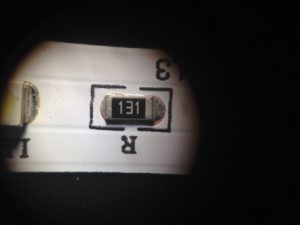
Control substrate (not immersed)
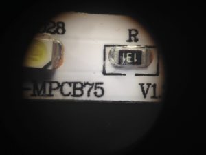
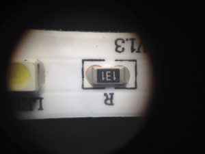
In the final test, the aforementioned LED strips were coated with both treatments and submerged under salt water while being powered up (12V source) for one hour. While both coatings performed well on the IPC-25A test boards, the silicone coating showed some serious spalling/corrosion at a resistor edge, indicating poor coverage. This illustrates the need for doing real device testing as most traditional conformal coatings were not designed to protect versus liquid water and therefore the tests used to ‘rank’ conformal coatings cannot be simply applied to water protection testing for electronic devices.

Silicone 1-part conformal coated, post-testing
Conclusion
In today’s competitive marketplace where the value of electronic devices, particularly smartphones is constantly rising (and therefore the risk of water damage rises concurrently), not having some kind of water resistance to the device is becoming a serious problem for device designers/manufacturers. However, application of the latest generation of hydro/oleophobic coatings can help these devices achieve longer lifetimes under ‘real-use’ circumstances where they are going to be subject to exposure to liquids.

Next-gen hydrophobic coating, post-test
