5 Design Tips to Achieve High-Speed Design Success
By EMA Design Automation Inc.
Electronics Engineering Software EMA EMA OrCAD OrCAD pcb design pcb design software softwareThe more complex a PCB design becomes, the higher the chances are of running into high-speed PCB design issues. Often, high-speed design problems will present themselves in specific ways that, to the untrained eye, may not be obvious to diagnose. These issues can result in late-stage changes, delivery issues, and unpredictable costs to your board. Therefore, it is extremely important to find problems as early as possible to prevent project delays. Here, our experts at EMA have compiled a quick list of tips and tricks you will need to achieve high-speed design success. 
- Impedance Values Must Be Consistent
One of the most common issues in high-speed design is that of noise created due to impedance mismatches. When this happens, the impedance values are not consistent, and the symptoms will manifest as signal ringing, delays, and reflections that all reduce signal quality. To correct the mismatches, locate and move problematic segments. Resizing trace widths or altering the stack-up directions may also be necessary. This problem can be easy to manage early in the design cycle but becomes costly if the design has progressed too far.
- Make sure Traces Aren’t Too Close Together
Another noise issue that arises is due to coupling errors. This means that the proximity of two signal traces are too close to one another. Coupling issues are a function of signal “edge” speed, and most issues occur within the rise and fall rates of your signal transmissions. Fast signals can victimize long parallel runs, creating unwanted noise. Narrow trace-to-trace spacing must be remedied, the stack-up may need to be altered, or the signal edges must be slowed down. Many of these issues will also have costly fixes when found late in the design or manufacturing process.
- Move Power and Ground Planes Around to Avoid breaks Under the Signal Path
The third noise issue many designers face is in return-path delays due to discontinuities. Return-paths are critical for good signal quality, so disruptions cause delay. Signal currents use the path of least resistance, and split planes will degrade the signal. As a result, the current is no longer smooth, and the return-path is lengthened. Additionally, unwanted radiated signal emissions (EMI) can occur from your board. To fix the issue, you can simply add more reference planes. In more complicated cases, move power and ground planes around to avoid breaks under the signal paths and create a smooth flow.
- Solve Impedance-Related Problems First
The other typical root cause of high-speed issues is that of timing, when the signal is not arriving at its destination within the specified time frame. Typical requirements involve times for signal arrival, signal stability, and signal state to be recognized, and when they are not met, the timing will fail. The issues here will be one of several things; phase mismatching, total and relative propagation delays, impedance mismatching, rise and fall time distortions, and threshold crossing distortions. Solving the impedance-related problems should be a top priority. Once these are corrected, measure the entire delay path for accumulated delay and solve them, then resolve any phase issues with differential clocking signals. Many of these fixes may result in board alterations, so it is important to catch these errors as early in the process as possible.
- Rules of Thumb Are No Guarantee
Our last fix is more of a word of advice, and that is: in PCB design, rules-of-thumb are a great starting point in your design, but they are no guarantee to finding related problems. When you lay out your board, a rule-of-thumb does not give feedback or a good vision of how your board will perform under set conditions.
There is a need for a more conclusive analysis system during the design cycle. Re-spins are costly, and when problems occur early on, they are often compounded all the way through to the end. Finding a good tool with real-time design fixes are a safe bet, and Cadence Real-Time Design can do just that.
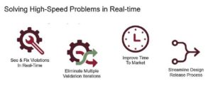
With Real-Time Design in OrCAD, you can control and manage your designs as you work, with system checks that will flag violations to be fixed before you send it on. Streamline your process and improve your time-to-market schedule, eliminating multiple validation iterations and boosting your productivity with Real-Time Design. Check out our High-Speed Design page for more information on getting started with the tool today.
