Advantages and drawbacks of the most common power management techniques
By Wilfried Dron is CEO & co-founder at Wisebatt
Electronics Power Supply / Management IoT battery Editor Pick IoT LDO load power switchBattery life is an important differentiator for IoT devices’ development. It must be taken into consideration right at the beginning of the design phase, as one of the main technical specifications. With some simple techniques, engineers can drastically improve the power consumption of their connected devices to reach the battery life expected by the market.
In this article, Wisebatt’s CEO Wilfried Dron shares five techniques that allow engineers to optimize the power consumption and the battery life of their devices. He compiled a non-exhaustive list of the most common power management techniques and explored their practical application, advantages and drawbacks.
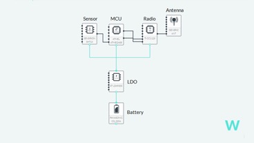
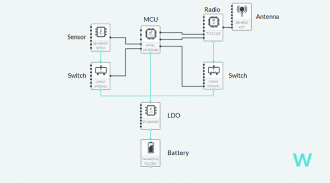
For this demonstration, we used a basic IOT device composed of a microcontroller, a sensor, a radio, a linear regulator and a battery. This is a 1h30 battery life long device which costs around 8 dollars for 1k units.
1- Use a LDO regulator
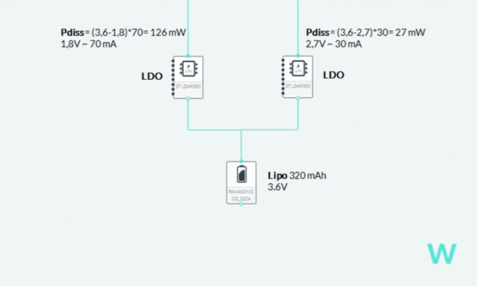
The first tip consists in putting another LDO regulator to lower the power consumption by splitting the power domain. It also helps to balance heat dissipation and wear level. There are two possible architectures:
The first one is a parallel architecture. The battery supplies the voltage to 2 regulators: one for each supply voltage rail. In our case, the power draw is unbalanced (126mW on the 1.8V rail versus 27mW on the 2.7V rail).
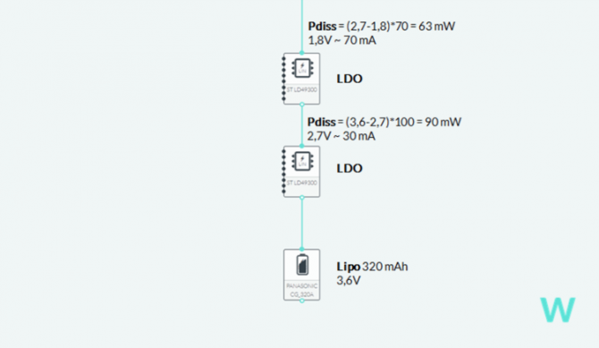
The second architecture is the follow-up topology. Each LDOs is placed one after the other. The first one is lowering the voltage to the highest supply voltage (from 3,6V to 2,7V) the second one is lowering the voltage even more from 2,7V to 1,8V. By doing so, the power dissipation is balanced between both regulators.
LDOs are very useful when it comes to sensitive applications (i.e. applications that are sensible to medium-high frequency noise). In addition, the efficiency will be higher when the input supply voltage is closer to the output supply voltage (considering the necessary drop). The last things that should be looked at when choosing a LDO are the “enable” and “bypass” features which can be very useful.
Advantages:
Using 2 LDO rails is a low noise solution which can expand devices’ battery life up to x1,5.
Drawbacks:
The efficiency relies on the ratio between the input supply voltage and the output supply voltage. Indeed, in some cases, the battery life could encounter marginal gains because of higher energy spent in the regulator.
Complexity:
This solution is fairly simple to implement, with a small footprint and few passives.
Cost:
The costs are low as this technique only requires the use of two passives: one at the input and one at the output (around 20¢ for the regulator and 3¢ for the filtering capacitor for 1,000 pieces).
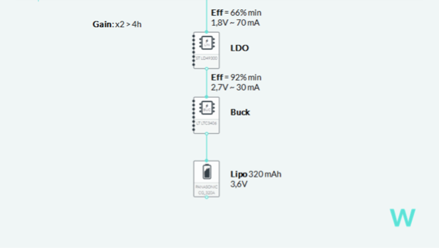
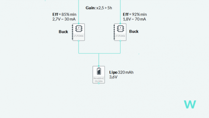
2- Use a buck regulator
With a follow up architecture, the buck regulator does most of the conversion by dropping the voltage from the battery from 3,6V to 2,7V. The linear regulator will further drop the voltage to 1,8V. This topology is particularly adapted to designs in which a part of the circuit is sensitive to switching noises. This part will be supplied with a LDO while a buck regulator supplies the other part.
The second architecture is a parallel topology, where both buck regulators are set in parallel. Unlike the LDOs, the buck regulator efficiency is less sensitive to the ratio between the input voltage and the output supply voltage.
Advantages:
With this second technique, the device can reach up to 2.5x battery life extension.
Drawback:
Buck regulators introduce a switching frequency which generates some noise on the power supply.
In addition, one must be careful while choosing a buck regulator as they may have very different quiescent current consumption.
Complexity:
The complexity of this solution is moderate as it just requires one additional passive (in comparison with the use of LDOs). In addition, it has a medium impact on the pcb footprint (the passive is an inductor and it could be bigger than the regulator itself).
Cost:
This technique is expensive. For instance, in the case that we demonstrate it could cost $2.2 per regulator and 20¢ + 2 x 1.4¢ for 1,000 pieces.
3- Use a load switch
The following technique consists in using a load switch in order to shut down all the unused components in the system, instead of putting them in sleep mode when not in use.
Advantages:
Using a load switch can lead to a gain of at least +10% of battery life, depending on the device’s application and the components that are shutdown.
Drawback:
It implies the use of a microcontroller GPIO which might be limited, depending on how many pins are already used. It also increases the firmware complexity.
Complexity:
This solution is very straightforward and has a small footprint, because it only demands to add a component between the power supply and the component that is load-balanced.
Costs:
This is a very low cost technique and can even be free when using the ‘enable’ feature of the regulator.
In the demonstrated case, it will cost 18¢ per switch for 1,000 pieces.
4- Power down unused peripherals
Powering down unused peripherals allows to minimize power consumption and leakage. Indeed, every small saving can lead to a substantial increase of the battery life.
Advantage:
This solution might drive to gain up to 2.5 times the initial battery life, which represents an important improvement, regarding the small changes it requires. Indeed, it demands only software modifications, while the hardware design can remain unchanged.
Drawback:
We might highlight the need to rewrite some existing software and drivers. This increases firmware complexity.
Complexity:
This approach is quite simple as it does not need any hardware modification.
Cost:
Free; except for the engineering time invested to be sure that everything is executed in the right order.
5- Get a bigger battery
If the previous battery life optimization techniques are not enough, the very last option would be to consider a bigger battery. However, this solution has no advantages.
Drawback:
Selecting a bigger battery will increase the device’s form factor, with a high probability of having to redo the mechanical casing. It might also require new certifications and consider specific rules (especially when the device must be delivered by airplane).
Complexity:
If the mechanical design is not determined yet, it is a quite simple technique.
Cost:
This solution is the most expensive one.
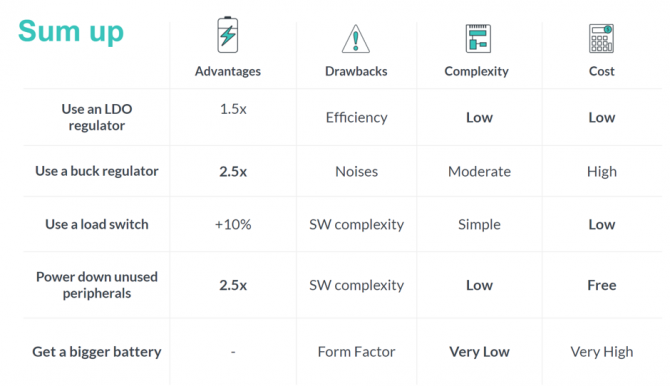
Here is a sum up of the five power management techniques introduced in this article.
The results come from my professional experience, as well as battery life estimations conducted on the simulation tool Wisebatt.
When battery life is an important constraint, IoT devices need to be designed to reach the most optimized power consumption. The various techniques introduced in this article can easily help engineers to improve their hardware design with a longer battery life. This non-exhaustive list shows the importance of considering various solutions to find the right adjustments for each specific device’s application. Those should be tested and estimated right from the first development steps to prevent any unnecessary design modification in the future.
—————————————–
Wilfried Dron is CEO & co-founder at Wisebatt in Paris France. Wisebatt’s technology estimates the battery life of a device by taking into account the entire system, its operation and its power consumption, as well as the non-linearities of its power source(s). Dron has a PhD in computer science, telecommunications and electronics.