Use of infrared thermography in electronics
By Sat Sandhu, thermography services manager, Fluke Corp.
Thermal management Engineering Supply Chain thermographyElectronic circuits and components come in a variety of shapes and forms. All electronics operate with current flowing, which in turn leads to power dissipation. This power dissipation manifests itself primarily in the form of heat. Hence a key factor in the design, tests, verification and troubleshooting of all electronics, is heat management. With increasing circuit complexity and or reduction in size, heat management of electronics is taking on a more significant role in the design phase and also in the subsequent phases of test, verification and troubleshooting.
Thermal imaging cameras (TI) are an ideal tool to use in mapping out the heat patterns on electronic circuits and components. Two major advantages of Thermal imaging over contact temperature measurement devices are:
1. The ability to measure temperatures without making contact with the circuit or component, thus ensuring that the temperature of the object is not affected.
2. The ability to view a large area or even the whole circuit or component, rather than measuring a single point.
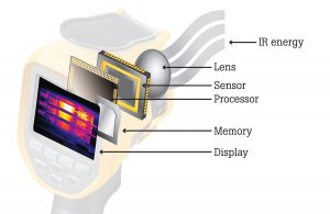
Figure 1: Anatomy of an infrared camera.
What are the sources of heat in electronics?
The power input to any electronic or electrical circuit is dissipated as heat. This heat dissipation will cause a rise in temperature above ambient. The temperature rise depends on a variety of factors. One of the primary factor will be the thermal resistance of the device; other factor include any thermal management, heat sinks, forced air cooling etc. Excluding the other factors lets us consider an example of thermal resistance only. A resistor is dissipating 300mW (0.3W) of power. Its thermal resistance is rated at 150K/W. Then this will give lead to a temperature rise of 0.3 X 150 = 45C. Assuming ambient of around 20C means that the temperature of the resistor will be around 65C.
If the resistor has an operating temperature range, of, for e.g., -55C to +155C, a component temperature of 65C may not be an issue. However on other components, the combination of the power dissipation and the thermal resistance may well bring the operating temperature closer to its specified operating range.
In addition we also need to consider other sources of heat in an electronic circuit. Shorts circuits; High speed switching, especially where the device is overclocked.
Why heat matters?
It is generally accepted that operating components at higher temperatures leads to higher stresses on components and circuits. This in turn can lead to increase in leakage currents, greater voltage drifts, increased propagation delays, increased chemical reactions in the material. All of these factors will lead to:
Shorter lifetime:
There is significant data that the lifetime of electronic parts is reduced by an increase in temperature. Whilst Reliability engineering offers many tools to estimate the lifetime of products, life is reduced with an increase in temperature referred to as Mean time to failure (MTTF) or mean time between failures (MTBF), the temperature of the product is a key and vital parameter in these calculations. Whilst there is a great deal of debate and discussion on the effect of modeling used to establish reliability based on the Arrhenius equation, what is certainly true is that elevated temperatures do affect lifetime. The general quick rule of thumb is that an increase of 10C reduces lifetime by half.
Greater risk of failure:
Like shorter lifetime, there is also significant data that increased temperatures also increases the risk of failure. An example of this on joints. The different metals will have different thermal coefficients: thermal cycling can then lead to strains and crack in joints.
Possible reduced performance:
An increased temperature can also affect the overall performance of an electronic circuit. Increased switching times, reduced resistances, increased leakage currents, all these factors can be enough to alter the overall performance of an electronic circuit.
Possible safety concerns:
The combination of greater risk of failure, reduced performance and a higher component temperatures can also potential lead to possible safety concerns.
Case study: Use of thermal imaging in the design phase
Electronic component vendors all must test their products to ensure that they perform as expected under specified conditions and to determine their typical performance life. For example, a manufacturer of surface mount resistors would want to ensure the performance, reliability, and typical life expectancy of the components it supplies.
The best way to accomplish that is to test the resistors at key points during design and development stages. A resistor is primarily a device that limits current or voltage and dissipates heat depending on the currents and voltages applied. Viewing the typical thermal patterns of a resistor under test with an infrared camera equipped with a macro lens allows a manufacturer to obtain extremely useful data about the design of the resistor and its behaviour as it dissipates heat energy. Those thermal patterns can indicate manufacturing related issues.
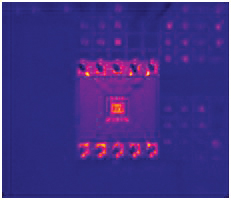
Figure 2: Unpowered resistor set lens.
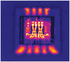
Figure 3: Unpowered resistor set with macro.
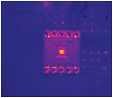
Figure 4: Powered resistor set.
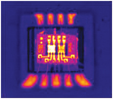
Figure 5: Powered resistor set with macro lens.
For example, Figure 2 shows an unpowered 400 ohm resistor on an ac-dc converter captured with a standard lens. Figure 3 shows the same component captured with a 25 micron macro lens. As you can see, the macro image provides much more detail about the resistor, even without power.
Next we powered up the converter and scanned it first with the standard lens (Figure 4) and then with the macro lens (Figure 5). The image captured with the standard lens doesn’t show any obvious problems.
However, the much more detailed image captured with the 25 micron macro lens shows that the right side of the resistor is drawing far less current than the left side. This then indicates room for further investigation. Either one of the pair of resistors is drawing too much current or the other one is drawing too little current. Temperature measurements are vital in calculating expected lifetime. The heat patterns of the resistor can be detailed enough to indicate hot spots.
Such hot spots are very likely outside the specified working temperature of the component and can accelerate stresses in the material leading to early failure. With the information gained from the thermal images, the engineer would be able to change the design or the manufacturing process to mitigate the stress points that are creating the hot spot
Case study: Use of thermal imaging in verification
A sensor company had a PCA designed to provide the high level of data processing required for its sensors. During the verification stage checking the PCA was inspected with a thermal imager where a hot spot was noted on a small component. On further investigation this hot spot was on a device and was around 85C. With the exception of the power supply devices and processor devices, which had heat sinks attached, the rest of the components on the board were all around 65C or less.
Given that this particular component was a power supply controller chip, with all of the large currents passing through external components, it is not expected to dissipate much power at all. It was then necessary to investigate what was causing such a high power dissipation in a part which was expected to require very little power.
Given that the measured package temperature of 85C was at about 23C ambient, then the part would be expected to be reach 122C at 60C ambient. This would then be very close to the specified maximum 125C junction temperature for this device.
The design team then requested all the testing parameters used. Once this information was available they requested the tests to be repeated at 12V. The device now no longer got as hot measuring 42C. Highest temperatures on the board were also now under 60C, which was much more reasonable. Unfortunately the end product cannot be operated from 12V, as the system uses 24V power supply.
Having identified the issue, various options were considered to resolve this matter. A redesign of the board was ruled out due to a combination of time, resource, cost and operation – cost both of the redesign and component changes that would be required. In addition was no suitable alternative to the ‘culprit’ device. The major deciding factor was that the modelling carried out clearly indicated that it would be difficult to get the desired lower temperatures by redesign only.
The other major solution then was to consider the thermal management of the PCA. As there was only one device of concern, it was decided to attach a heatsink to it.
The addition of a heat sink now increased the cooling effect giving a lower overall package temperature.
Conclusion
The two case studies described above illustrate the power of using thermal imaging in the thermal management aspect of electronics. In both instances using contact temperature measurement would have been cumbersome and very time consuming. In addition in the case of the unbalanced current flow in the resistors the small size meant this could and would not have been identified.
In the second case the effect of the probe touching the small IC may well have led to some cooling effect which in turn could easily report a slightly lower temperature. This lower value could have been enough to assume that this is not as critical.
With the decrease in component sizes and increased performance demands, heat management of electronics devices and circuits is becoming more significant and important. Thermal imaging is proving to be an ideal tool in helping in the design, verification and troubleshooting of electronics.