Application of solder ball technology on QFP pads improves processing reliability
By Advanced Interconnections Corp.
Interconnect Engineering Supply Chain BGA solder ball technologyIC complexity and higher I/O counts have pushed older technology like Quad Flat Pack packages (QFP) to the limit of finer pin placement. Solder bridging between closely spaced gull wing leads of fine pitch QFP packages presents a significant yield issue in production.
This, along with other challenges associated with QFP packages such as non-coplanar leads ‘lifting’ after reflow, opened the door for newer, high density packages, such as Ball Grid Array (BGA), that are ultimately more cost effective and process friendly.
Fig. 1 – Conventional adapters depend on ‘gull wing’ leads to attach to the existing pcb land design. In some cases, coplanarity issues reach a critical point when four individual lead frame add-ons are used to breakout a new BGA footprint to an existing QFP pad layout.
Until recently, however, the only options to accommodate device transition from QFP to BGA were to re-spin boards or purchase a custom package conversion adapter employing lead frames that match the rectangular pad layout on the existing printed circuit board (pcb). Conventional adapters using lead frame technology inherently pose the same reliability and processing issues (solder bridging, coplanarity, etc.) associated with the end-of-life QFP devices. (see Figure 1).
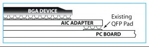
A robust alternative has been developed for using BGA devices on boards designed with QFP pads. This patented technology employs the advantages of the BGA package directly on the board interface – eliminating the design weaknesses and processing challenges associated with gull-wing leads, while allowing uninterrupted production using existing board inventory. Advanced Interconnections Corp. has extended its field-proven solder ball attach process from BGA Socketing Systems to a new interposer design that replaces traditional lead frames with a solder sphere interface. The streamlined interposers maintain the existing board layout while seamlessly converting BGA packages for use on QFP footprints. (See Figure 2)
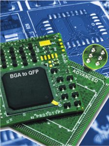
Fig. 2 – A series of solder balls are applied to the bottom of the adapter/interposer, in the same pattern as the QFP footprint using a patented process. Existing board inventory is maintained, and processing issues caused by fragile leads are eliminated.
The patented technology can be applied to cover a wide range of package types and footprints; BGA and PGA can be converted to the original QFP pad layout as well as adapting finer pitch QFP packages to older designs.
The solder ball interface on the bottom of the interposer provides a robust attachment that exceeds QFP process yields by employing a predetermined number of solder balls in place of the traditional lead frame, producing a consistent, reliable solder fillet. With multiple balls for each QFP pad, there is redundancy in the design, virtually eliminating the possibility of a bad solder joint or fracture. Also, this system minimizes coplanarity issues among the pads themselves for further processing reliability.
Additional Benefits Higher density BGA packages are much smaller than their QFP predecessors, leaving room on the interposer to include a mix of additional active and passive surface mount components to enhance the product design or accommodate other changes to updated ICs. (See Figure 3)
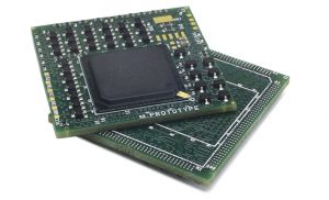
Fig. 3 – QFP Package Conversion Adapters maintain the ‘keep out’ areas of the original design, so there is no board space penalty from adding components.
In addition to device obsolescence, QFP Interposers & Package Conversion Adapters also solve issues associated with the transition from tin/lead to lead-free packages. In a recent application, the only replacement for the original tin/lead QFP device was a lead-free BGA package. The customer wanted to maintain its existing, fully qualified tin/lead reflow profile. Advanced deployed eutectic tin/lead solder balls on the QFP interface to the customer’s PC board.
However the interposer board assembly was first processed using a high temperature, lead-free device attach process. The two-step interposer assembly process helped the customer avoid costly interruptions to its supply chain and eliminated the need to requalify the reflow process. Conclusion Having a reliable alternative to either re-spinning boards or using custom adapters that have the same processing challenges as the device packages they are replacing will save time, cost, and ease inventory management issues for electronic OEMs dealing with device obsolescence.
The patented Solder Sphere Interface technology from Advanced Interconnections addresses a wide range of issues from QFP device obsolescence, to lead-free transitions, to the device enhancements and corrections. The innovative solution ensures that existing boards can be used with current reflow processes, while improving processing results and providing a more reliable solder joint.