Understanding power supply measurement throughout the design process
By Varun Merchant, mainstream technical marketing manager, Tektronix Inc.
Power Supply / Management Engineering power measurement power supplyThe pressure on designers to create efficient, inexpensive, sleeker and smaller power supply designs is more intense than ever before. Power supplies are the lifeline behind all electronics and electronic devices. However, higher efficiencies, higher power densities, time to market, standards requirements and cost reductions are impacting designs and designers alike. That’s a lot to think about. But take a breather and follow along in this article as we outline the power supply design process and run through the test requirements at each step along the way.
Component manufactures usually provide designers with detailed datasheets, containing the necessary operating characteristics for a good power supply design. In many cases, component selection could be made on datasheet parameters alone. Unfortunately, increasingly rigid requirements on new designs occasionally require the designer to characterize components beyond the standard datasheet parameters.
When working with critical power components such as MOSFETs, IGBTs and diodes, select an optimized key parameter. The optimized key parameter could be an on-state, off-state or an AC characteristic. Next, test your components across all temperature ranges—well beyond the ideal conditions stated in the data sheet. Finally, test the passive and active components for real world conditions.
The next stage in the design cycle is prototyping. Be aware that prototypes are prone to failure. Numerous things can go wrong with board routing, solder joints, component placement and hidden parasitics, so proceed with caution. Before powering on, always use a digital multimeter to check for shorts across all the input and output stages. Once that is completed, isolate the low-voltage analog and digital circuit into as many sub-circuits as possible and power up the prototype board one sub-circuit at a time.
Now you can isolate the on-board power supply and test the output with and without a load. After that is complete, check if the output voltage and ripple are what you expected. Lastly, use a precision DC power supply to power on individual low-voltage sub circuits. Don’t just rely on the on-board power supply. If the on-board power supply has multiple outputs, we suggest using a DC power source with multiple isolated channels such the one shown in Figure 1.
For an on-the-spot reality check, use a DC power supply that shows both the programmed settings and the actual measured outputs simultaneously which will allow you to quickly determine if the DC stages are drawing too much current.
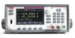
Figure 1: For testing an on-board power supply with multiple outputs, you’ll need a dc power supply with multiple isolated channels.
High-voltage ac circuit power-on
Now that all of your low-voltage dc circuits are checked out, it’s time to power-on the high-voltage circuits. This is the stage where your prototype will see high voltage for the very first time. It’s always a good idea to isolate high-voltage stages from low-voltage stages during the first power-on. We suggest using an AC power source with current limiting. It’s crucial to always start from the lowest AC voltage for your design to help reduce major blowouts, which can occur from bad soldering, poor assembly or PCB design mistakes.
Assuming no major catastrophe has occurred, measure the AC input voltage and current with appropriately-rated differential and current probes. Use a scope or a power analyzer on the AC input with logging enabled before powering on the device for the first time to capture the inrush currents and transients. If the high-voltage power stage checks out, you can enable the low-voltage control circuit, which will provide a complete picture.
Control circuit debugging
Now let’s move on to digital and analog control circuit debugging. This is the stage where you check the control logic—probably the most important, not to mention, complex part of the design. In this stage, you need to test for proper compensation, voltage, timing and frequency responses. First, verify proper switching frequency, pulse width and duty cycle at different loads. To do this properly, measure the modulation signal at the switching device driver during power-on. Next, check the loop frequency by injecting a frequency sweep signal through a wideband injection transformer in the control loop. Lastly, use a frequency response analyzer to measure the gain and phase of the circuit.
After the high-voltage circuits, low-voltage circuits and control logic have been verified, it’s time to check the switching characteristics of the power stage. Start by testing the switching characteristics at no load, nominal load and full load Always double-check that the turn-on, turn-off, duty-cycle and dead-times of all switches (MOSFETS, IGBTs, etc.) are as expected. Also check the VGS signals for noise and bumps. This is important because any unintended glitches on this terminal can lead to turn-on and shoot-through.
Depending on the topology, you should also check the dead-time for sync rectifiers or H-bridges. This process will help ensure that there’s no possibility of shoot-through. In order to guarantee that everything is as expected, verify the timing relationships among gate drivers and other related signals.
Since efficiency is usually the primary design goal, it’s crucial to minimize any losses that might have been introduced during the design process. Be aware that switching and conduction losses through power switches and magnetics are major contributors to the overall loss of a system, especially for modern high-efficiency designs.
To be safe, we recommend against simply calculating switching and conduction losses based on a datasheet as this can not only be misleading, but also wildly off-base. The reason is that datasheets don’t provide a comprehensive loss profile accounting for operating conditions and circuit parasitics. Make sure to also check the rectifier, switches (MOSFETs, IGBTs, etc.) and magnetics for losses when the circuit is active and loaded. More often than not, magnetics are custom-designed and, just like switching devices, they’re important to test during operation. This process will help to ensure that the magnetics are properly characterized.
To measure switching loss on an oscilloscope, you can multiply voltage by current and take the mean of the resulting power waveform during turn-on or turn-off. The use of power analysis software as shown in Figure 2 makes this process easier and more repeatable.
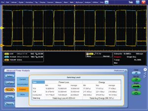
Figure 2: Power software automatically performs switching and conduction losses.
Specification check
Now it’s time to determine whether or not your design meets certain key specifications, such as line and load regulation, ripple, noise, short-circuit protection, transient response and efficiency.
For load regulation, it’s best to use a high-precision DMM directly on the input and output terminals of the power supply. Then sweep the load from minimum to maximum while keeping the input voltage constant during the test. This is very important to ensure consistent results. Be sure to log any changes in output voltage versus load to determine load regulation.
Next, move on to line regulation, which can be tested with a similar setup. Output voltage is measured across a constant load, while input AC voltage sweeps from minimum to maximum. This test is especially critical for universal input power supplies. Now check for noise and ripple at full load using a scope that’s optimized for high-resolution measurements or a high-precision graphical sampling multimeter. Although, the scope will provide higher bandwidth, the multimeter will give better accuracy. It’s also helpful to log efficiency using a power analyzer while sweeping the input voltage and output load through all the operating conditions.
Now that your prototype is up and running, it’s time to see if the design will comply with local power line standards. Most AC-DC power supplies are designed to operate from an AC wall socket. The AC-DC power supplies are also subject to stringent power consumption and power quality standards, such as IEC 62301 standby power and IEC 61000-3-2 current harmonics standards. Compliance with these standards should be tested early in the design cycle to avoid future headaches. Also, make sure that the power analyzer that you’re using for testing current harmonics complies with the IEC 61000-4-7 standard for measurement techniques.
When measuring low and distorted standby power, be sure to double-check your connections as incorrect wiring can lead to significant errors. Make sure you always connect the voltmeter channel on the source side of the current shunt so you don’t measure the current through the voltmeter impedance.
EMI and RFI testing
Far too often EMI and RFI testing is overlooked in the early design stages due to difficulty and expense. However, this stage should never be ignored as you could find yourself stuck with unpleasant surprises and delays as your deadline looms. Make it a habit to test for EMC issues early on in the design cycle. This will help you to avoid unnecessary board turns and missed deadlines.
Fortunately, EMI testing is simple and fast. Grab a spectrum analyzer and a pre-defined EMI compliance mask to perform the necessary tests to catch those pesky EMI problems before you go to the test house later on in the program. To quickly localize sources of EMI, try using a mixed domain oscilloscope (MDO) with a built-in spectrum analyzer and near-field probes as shown in Figure 3. Armed with your oscilloscope and a schematic, you will be able to measure the spectral peaks and deduce root causes.
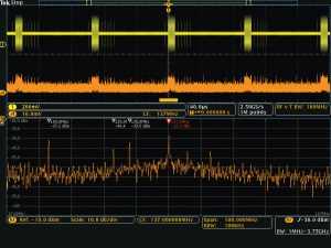
Figure 3: A mixed domain oscilloscope such as the Tektronix MDO4000C speeds EMI troubleshooting by showing synchronized time and spectrum traces.
Once you’ve thoroughly tested your first prototype, it’s time to shift into overdrive and go for the next revision. As a sanity check, thoroughly repeat all of the testing steps. Once everything checks out, it’s time to check reliability. Test the power supply for all input configurations, which is especially important for universal-input power supplies. Next, sweep the load from no load to full load in order to test your power supply for all conceivable operating conditions. Finally, run a lifetime test using environmental chambers, which check the real-life performance of your design.
If you have followed the measurement steps design process outline here, you’re well on your way to delivering a highly efficient, reliable and compliant power supply.