Putting the control in programmable logic controllers
By Atul Patel, product marketing, high volume logic system connectivity, Texas Instruments
Semiconductors Engineering logic controllerProgrammable logic controllers (PLCs) are the workhorse computing systems that help to coordinate and harmonize functions performed by the multitude of sensors, actuators, conveyors and many other electromechanical devices that are found in a modern factory setting. As the name implies, programmable logic controllers communicate software-based instructions to the various subcomponents and subsystems that comprises the PLC.
Have you ever wondered how the various components of a PLC communicate with one another? PLCs use many different interface standards for communicating different types of data. The inter-integrated circuit (I2C) bus is one of the key control interface standards used by PLCs that enables the communication of control information between the various devices and modules that makes up a PLC (Figure 1).
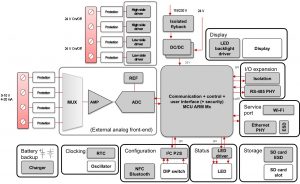
Figure 1: PLC system level- communication of control data between the different sub-modules that makes up a PLC is often through a control bus such as I2C, SMBUS, or SPI.
I2C has been around for many years and it has become the go-to control interface standard for most electronic systems designers. I2C consists of a simple two-wire bus interface where one wire carries serial data (SDA) and the other wire carries a clock (SCL) signal. I2C is a shared bus environment where various system components that need to exchange data simply connect to the two bus lines and then follow a simple defined arbitration protocol to gain access and send data on the bus while other devices listen to the bus. In complex systems like PLCs, I2C buses often need to be extended to the next level in order to accommodate multiple sub sets of devices on multiple boards. System designers can extend the capabilities of their I2C implementation by using simple devices such as I2C level translators, buffers, general purpose input/output (GPIO) expanders, and I2C muxes/switches.
I2C level translators (also referred to as I2C level shifters) help design engineers quickly link together components via an I2C bus even though the components may be on different voltage domains. I2C level translators can save system designers a lot of engineering time when selecting components for their system by allowing them to select devices best suited for the task rather than compromising on a feature in order to align on control I/O voltage levels.
For certain PLC applications, such as the main controller board, I2C level translators can be indispensable given the multitude of different device types and voltage rails that need to be supported. In some PLC implementations, engineers have to contend with I2C buses that are capacitively loaded beyond standard recommendations of 400 pF. In these cases, a simple I2C buffer can be used to help “increase” the loading budget on the bus to allow for more loads to be added without affecting the overall signal integrity of the I2C bus (Figure 2). I2C voltage translators and buffers are available in a wide array of configurations and voltage ranges giving design engineers many possible solutions.

Figure 2: I2C buffer use case.
Another type of I2C device that design engineers turn to for help in tough design situations is an I2C IO expander. IO expanders basically enable a system designer to increase the general propose input/output (GPIO) lines available on the system processor. IO expanders are especially handy when the scope of a project changes and new features and functions are added after processor selection has been finalized and the system partitioning has been completed. IO Expanders often allows a design engineer to accommodate new features by simply adding more GPIO that can be provisioned to meet the new requirements (Figure 3).
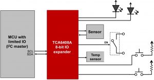
Figure 3: IO expander use case example.
For PLC designs where processor selection is a critical control point, using IO expanders can save the system designer from having to select a new processor with more GPIO and then having to rework system partitioning and the system software. It is easy to see how IO expanders can be a life saver for systems designers when requirements change. IO expanders are available in a wide range of IO counts, enabling system designers to optimize the amount of GPIO they add to their system.
PLC systems frequently incorporate multiple types for sensors and other peripheral devices that are often connected to the system via a control interface, such as an I2C bus. It is common that industrial systems will need to support multiple copies of a component such as a temperature sensor. Having multiple copies of the same device on an I2C bus can pose a design challenge as these devices can share the same I2C address which results in address conflicts.
Design engineers have to go to great lengths to resolve address conflicts taking up precious engineering time and resources. Address conflicts are especially cumbersome to resolve in industrial systems such as PLCs where many peripheral devices may share a control bus such as an I2C bus. One solution that engineers are turning to more often are I2C switch devices.
An I2C switch device connects to and multiplexes the main I2C bus to multiple new I2C bus ports one port at a time. For example, a 1:8 I2C switch will be able to connect the main I2C bus to one of eight different I2C bus ports. In the case where multiple devices have the same I2C address, the devices can be segregated to their own I2C bus (port), and then each port can be referenced individually by switching to the appropriate port.
Using an I2C switch device enables design engineers to segregate devices, with the same I2C address, to its own I2C bus thereby avoiding any possible address conflicts (Figure 4). An additional benefit of I2C mux devices is that they also can be controlled by I2C, reducing the need for additional GPIO on the application processor. I2C switches are available with multiple port count options, and in many cases multiple I2C switches can be added to a single I2C master bus.
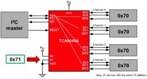
Figure 4: I2C mux use case example.
The extensibility brought to the I2C standard by simple devices such as I2C level translators, I2C buffers, GPIO expanders, and switches is helping PLC system designers bring together the multitude of different devices that makes up modern programmable logic controllers. In fact, the PLC example can be extended to a wider scope of applicability for systems in consumer, communications, automotive, computing and many other market spaces.
I2C control bus implementations are likely to become even more critical for designers as they are faced with making products with more features at lower cost points with more power efficiency. Taking advantage of all that the I2C standard has to offer can truly help a system designer get their design under control.