Modular connectors help industrial test equipment users reduce operating costs
By ODU-USA Inc.
Automation / Robotics Interconnect Test & MeasurementMost personal computer users appreciate how frustrating it can be to install or remove the numerous cables that need to be connected to their PC’s rear panel to support diverse devices, such as screens, keyboard, mouse, printers, etc. Fortunately for PC users, connecting or disconnecting cables is an infrequent operation, and their ‘cable chaos’ is typically hidden away under a desk.
Industrial test equipment is a different story, as the number and diversity of cables can be many times greater than required for even the most complex PC configuration. The recent advent of configurable modular connectors has not only reduced cable chaos, but helped industrial test equipment users to streamline operations, improve safety and reduce costs.
This article examines the characteristics that make modular connectors such a valuable component in testing environments, and briefly reviews products from four different vendors.
Introduction
When a leading supplier of wafer fabrication equipment and services to the global semiconductor industry, urgently needed a high-current modular connector for its new fabrication system they contacted numerous vendors. In the end, that firm selected the ODU-MAC series modular connector system because of its configuration flexibility, very high mating cycle performance and its volume availability.
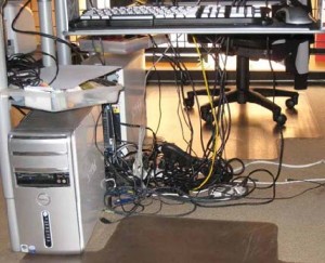
Figure 1: Cable chaos in an industrial environment.
That company’s requirement is typical of many industrial applications today, in which efficiently designed cabling systems can play a major role in the profitability of the overall system. Consider for example, an automotive production line, in which adjustable vehicle seat assemblies must be tested as rapidly as possible as they reach a particular test station. The station contains test equipment and a power source that must be dynamically connected to each seat via multiple cables. Once the tests are complete, the cables must be disconnected, in preparation for arrival of the next seat assembly. This operation is repeated every few minutes, on a daily basis. The more rapidly those cables can be connected and disconnected, the higher the number of seats that can be tested each day. Traditionally, the complexity of mating and un-mating the multiple separate cables has necessitated a human operator but with the correct interconnect can be automated as well.
Rapid cable connection/disconnection capability is not the only factor in the efficient operation of the test station. The cable connectors themselves must be capable of a high number of mating cycles, so that the line can run without interruption for months at a time. Moreover, when the inevitable connector failure does occur, rapid repair or replacement capability is essential to avoid production line shutdown.
In this paper, we will examine the solution to these cabling and connector challenges, as well as the factors that differentiate the products from four major connector manufacturers.
Cable chaos
We’ve all experienced cable chaos at some time or another (Figure 1). In many industrial environments, however, the same is not true – especially in testing environments, where operators may need to connect and disconnect multiple cables and hoses on a routine and frequent basis. In this case, cable chaos can directly result in loss of productivity, safety issues and even emergency production line stoppage.
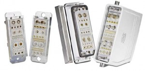
Figure 2: ODU-MAC series of connectors.
Eliminating the chaos
Fortunately, recent developments in technology have provided improved solutions, such as the modular connector. Figure 2 shows the diversity of different connector types in the ODU-MAC series. In the event of any single connector failure, its module can be easily removed from the mounting frame and replaced.
In addition, the ODU-MAC Series offers six standard docking frames in various sizes and floating behavior, as well as a housing option with a choice of locking mechanisms. The frame models are used exclusively for automatic docking applications, while the housing models are used in applications that require manual mating. Particularly noteworthy is the ‘P’ Power frame model designed for use with power connector modules. Its large guide pins guarantee safe and secure docking when high voltages or currents are present.
When an equipment manufacturer needs to select the most suitable modular connector, there are several functional and operational characteristics to consider:
Functional characteristics
* What types of connection interfaces are supported?
* How diverse a range of docking frames and sizes are offered?
* How many connections can fit into the frame?
* How easy is it to configure a complete connector?
* Are there any module combination restrictions?
Operational characteristics
* How easy is it to connect and disconnect the male and female units (as measured by the mating and un-mating forces required)?
* How quickly do contact pins and sockets begin to degrade (as measured by the increased electrical resistance between contact pairs, and the diminishing force required to mate and un-mate the connectors)?
* How many connect/disconnect cycles can be executed before a complete failure occurs?
* Can damaged modules be repaired in the field (e.g. by replacement of individual pins), or must they be scrapped and replaced?
* How quickly can individual modules and contacts be replaced?
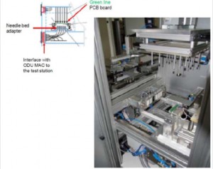
Figure 3: PCB test station.
Practical applications
A wide range of manufacturing and testing industries have embraced the use of modular connectors as a means of streamlining their operations, as well as reducing manual labor. One example is within the electronics industry itself.
In the electronics industry, reliability is a key ingredient of successful products and so testing is essential throughout the manufacturing processes of electronic components. Two examples of this are presented here. Figure 3 shows a printed circuit board (pcb) test station, at which a bed of ‘needles’ is lowered onto the board under test. Each needle touches a specific measurement point on the board, feeding back information to the test monitor via a single bundled cable and modular connector. Since parameters such as continuity, resistance, capacitance and other basic electrical characteristics are being measured, it is important that the modular connector itself adds virtually no additional impedance to the measured values. The connector must also offer high contact capacity, to accommodate the large number of test points that may be present on a complex circuit board.
As in this example, very low contact resistance and high contact density are important characteristics of the modular connectors used in the enclosed production line. However, additional characteristics are essential in this case. They must also be capable of operating reliably in the sometimes extreme simulated climate conditions, and they must have a high mating cycle capacity.
Conclusions
Although the mechanical technology of modular connectors may seem like a less exciting subject than the sophisticated computer technology with which it is frequently partnered, there are many industrial applications that depend heavily on the reliability and operational efficiencies it enables.