Modern design tools make it easier to tune DDR4 signal paths
By Ben Jordan, product manager, Altium Ltd.
Embedded Systems EngineeringThe latest standard in the race for ever-denser and ever-faster dynamic RAM is DDR4, short for double data rate, fourth generation synchronous dynamic random-access memory. DDR4 memory will operate at speeds between 1600 MHz and 3200 MHz, compared to speeds between 800 MHz and 2400 MHz for DDR3 memory. Standard memory modules will be denser, too. The DDR4 standard specifies DIMMs up 128 Gbytes, compared to a maximum of 16 Gbytes for a DDR3 DIMM.
DDR4 modules employ a hybrid topology. DDR4 designs have parallel, length-matched transmission lines for the data bus and daisy-chained, length matched transmission lines for the clock, address, and control bus lines. The latter type of topology is sometimes called “fly-by” topology. Each signal is routed sequentially from one device to the next, and is then terminated after the last device.
Signal delay increases for each successive device
This topology eliminates reflections, but the downside is that the signal delay increases for each successive device in the chain. This topology is used when the output device can compensate for this signal skew, using a technique known as signal leveling.
Figure 1 shows how an address or control line would be routed to each of the SDRAM devices on a DDR4 dual-inline memory module (DIMM). The lengths of the bus connections from connector to first device, and from device to device, must be tuned so that commands arrive at each chip center-aligned to the clock. The DDR4 specification spells out the timing requirements for each of the segments of this address or command line. Each segment must be treated as a transmission line. That’s why the segments are designated as TL0, TL1, etc.
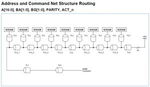
Figure 1. DDR4 DIMMs use a “fly-by” topology for address and control lines.
To ensure that the DDR4 module will work properly, you would first tune the length of the signal path from the DIMM connector to the first SDRAM device. This path includes TL0, TL1, and TL2. Once that path has been tuned you then go right down the daisy chain, tuning the paths between devices. The signal path from the last device in the chain to the termination, which includes TL5, does not need to be matched to the other sections, but its length should be limited so that the line is properly terminated.
Signal paths from device to device can simply be duplicated
If the devices on the DIMM are positioned the same distance from one another, the signal paths from device to device can simply be duplicated. This only works, however, if the signal lines are on the same board layer. If the lines run on different layers, the transmission line characteristics may differ enough so that the delay times do not match.
As you can imagine, trying to do this length tuning manually would be a very difficult task. That is why most modern PCB design tools include features that help the designer. In our tool, Altium Designer, this feature is called xSignals.
Using xSignals, designers define paths between two nodes. The two nodes can be nodes within a net, or they can be two nodes in associated nets separated by a component. Once defined, the designer can then specify various design rules applied to those signals, such as Length and Matched Length. As the board layout proceeds–in this case the layout of a DDR4 DIMM–the software will ensure that those design rules are followed, and that those signal paths meet the DDR4 specification.
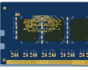
Figure 2. The signal lines on this DDR4 DIMM don’t follow the shortest path between SDRAM devices so that the delay times meet the DDR specifications.
The result is shown in Figure 2. The signal lines don’t follow the shortest route between the two SDRAM devices. Instead, their lengths are adjusted so that the delays are matched and meet the DDR4 specification. This would be an almost impossible task to do manually, but with modern design tools the job is a lot easier.