Choosing inductors for energy efficient power applications
By Len Crane, senior technologist, Coilcraft
Electronics Power Supply / Management Engineering ac/dc converters Current dc-dc inductors management powerEnergy efficiency can be as much about the inductors as the circuit topology
In high frequency dc-dc converters, power inductors filter out the ac ripple current superimposed on the dc output. Whether the converter steps the voltage down – buck – or steps the voltage up – boost – or both up and down – SEPIC, the inductor smooths the ripple to provide a pseudo-dc output.
For battery powered applications, battery life is extended by improving the efficiency of the entire power supply circuit, and inductor efficiency is often a major consideration in the design. Careful consideration of inductor efficiency can mean the difference between having your battery work when you need it and having to stop in the middle of an important task to plug it into a charger.
Inductor efficiency is highest when the combination of core and winding losses are the lowest. Therefore, the goal of highest efficiency is met by selecting an inductor that provides sufficient inductance to smooth out the ripple current while simultaneously minimizing losses. The inductor must pass the current without saturating the core or over-heating the winding.
Accurately predicting core and winding loss of an inductor can be complicated. Core loss depends on several factors, such as peak-peak ripple current, ripple current frequency, core material, core size, and turn count. The required ripple current and ripple current frequency are application-dependent, while the core material, core size, and turn count are inductor-dependent.
The most commonly-used equation to characterize core loss is the Steinmetz equation:
Pcore = K(f)x(B)y Where:
Pcore = power loss in the core
K, x, y = core material constants
F = frequency
B = flux density
This equation shows that core loss depends on frequency (f) and flux density (B). Flux density depends on ripple current, so both are application-dependent variables. It also shows that the core loss is inductor-dependent, where the core material determines the K, x, and y constants. Note that flux density is also a function of the core area (Ae) and the number of turns (N), therefore core loss is both application-dependent and inductor-dependent.
By comparison, dc winding loss is simple to calculate: Pdc = Idc2 × DCR
Where:
Pdc = dc power in Watts dissipated
Idc = Effective dc (rms) value of the inductor current.
DCR = dc resistance of the inductor winding
The ac winding loss is more complicated and may include the effects of increased resistance at higher frequency due to both skin effect and proximity effect. ESR (effective series resistance) or ACR (ac resistance) curves may show some of the increased resistance at higher frequency, however, these curves are typically made at very low current levels, so they do not capture current-dependent (core) loss. They are also subject to possible misinterpretation.
For example, consider the ESR vs frequency curve shown in Figure 1, which indicates that the ac resistance looks very high above 1MHz. This strongly suggests that this part would have very high ac loss. However, it has been observed that inductors with typical curves like this have performed very well in actual converters – much better than would be suggested by these curves.
Consider a buck converter that has an output of 5V at 0.3A (1.5 Watts). Selecting a 10µH Coilcraft inductor with a typical ESR vs frequency as shown in Figure 1, shows an ESR of about 0.8 Ohms at 250 kHz operation. The average inductor current equals the load current: 0.3A.
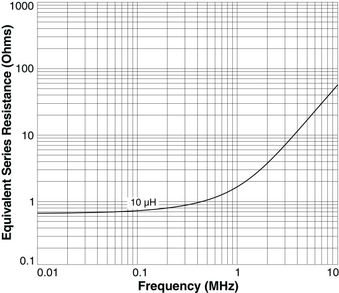
Fig. 1
We can calculate the loss in the inductor as I2R = (0.3 A)2 × (0.8Ω) = 0.072 W. 0.072 W ÷ 1.5 W = about 5% of output power lost in the inductor.
If we run the same converter at 5MHz, the ESR curve shows R is between 10 Ohms and 20 Ohms. If we assume the best case R = 10 Ohms, the calculated power loss is: I2R = (0.3 A)2 × (10Ω) = 0.9W, which is 60% of the output power lost in the inductor! Switching converters achieve far better performance than the ESR curves apparently predict. How? – In typical applications, ripple current is kept to approximately 40% of the load current or less. In the 5MHz example, it was assumed the current was all ripple current (ac).
Regardless of ripple content, ESR curves are based on very low current measurements and therefore they do not capture current-dependent core loss at higher current. Total inductor loss determines the overall inductor efficiency. Improvements in core materials have led to inductors with very low ac loss at high frequency, resulting in higher inductor efficiency. Therefore, inductor manufacturers optimize inductor efficiency by selecting low loss materials and rectangular ‘flat’ wire (for lowest DCR) to minimize total loss.
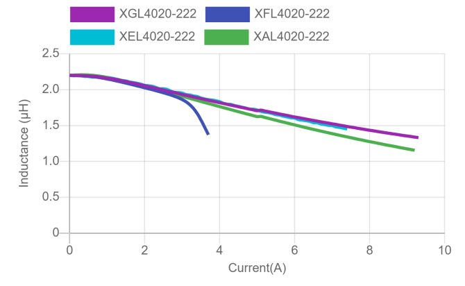
Fig. 3
Figure 3 shows the inductance vs current characteristics of the 2.2µH value in the XGL, XEL, XAL, and XFL Series. The XGL, XEL, and XAL series are clearly the best choice for holding inductance at around 3A or higher current. Table 1 compares the DCR and Isat of these inductors.
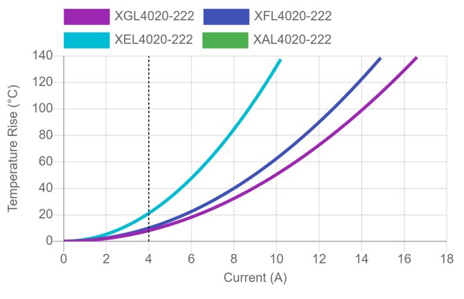
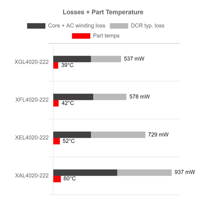
Figure 4 compares the AC loss and total loss of the same inductors at 2MHz. The XGL utilizes an innovative construction that exceeds all previous designs, resulting in a combination of the lowest dc and ac losses. This makes the XGL family the best choice for high frequency power converter applications that must withstand high peak current with lowest dc and ac losses.
To speed up the design process for engineers selecting inductors, Coilcraft has developed tools that calculate measurement-based core and winding loss for each possible application condition. The results from these tools include current-dependent and frequency-dependent core and winding loss, eliminating the need to request proprietary inductor design information, such as core material, Ae, and number of turns, and the need to perform hand calculations.
If your application is a dc converter, the Coilcraft dc-dc Optimizer Tool calculates the inductance value, peak current, and peak-peak current requirements, based on your operating conditions and the amount of AC ripple current you choose. It then feeds this information into our Power Inductor Finder tool to display a list of inductors that may meet these requirements. The list includes the inductance at peak current, current rating, total losses, and resulting part temperature for each inductor listed.
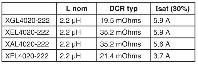
Table 1
If you already know the inductance value and current ratings required for your application, you can enter this information directly into the Power Inductor Finder. The results include core and winding (total) loss and saturation current ratings for each inductor, to verify that the inductance will remain close to the design requirement at the peak current condition for your application.
The tool may also be used to graph the inductance vs current behaviour to compare traditional hard-saturating inductors to soft saturation types. To select the highest efficiency inductor, the results can be sorted by total loss. Multiple sorts allow selection by multiple parameters.
Inductor loss is closely related to core size and wire size. In many cases, lowest loss corresponds to larger part size, or it corresponds to using a hard-saturation (ferrite) core material at lower switching frequencies. As with any design, there may be compromises that require analyzing trade-offs in size or inductance at peak current vs efficiency. Having all of the inductor information in a complete list that allows multiple sorting facilitates such an analysis.
Conclusion
Designing for highest efficiency performance requires selection of inductors with the lowest total loss at application conditions. Calculating total loss can be complicated, but these calculations are built into the Coilcraft power magnetics tools, making selection, comparison, and analysis as simple as possible.