Clarifying the status of LED indicators in fuse terminals
Staff
Circuit Protection Electronics Optoelectronics CEL Circuit CLSI control Current DEPRO fuse Indicators LED Sensing systems terminalsFuse holders used in industrial applications, whether fuse terminal blocks or modules, often include a status LED. So if the LED is on, is the fuse blown or healthy?
Status LEDs may indicate the fuse is healthy or may energize if the fuse fails and thus indicate a blown fuse.{nomultithumb}
Fuse healthy indication requires a neutral or 0V connection. The LED circuit is located between the load side of the fuse and neutral or 0V. Often a green LED is used but red LEDs are also common. 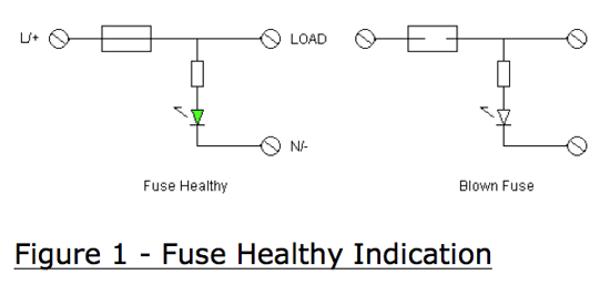 In control systems, if the terminal is located between the power supply and the digital I/O the indicator will show the fuse status regardless of the state of the I/O. For example, a fuse may be located between the power supply and a transistor output on a PLC. The output does not need to be energized for the fuse healthy indicator to operate.If the fuse terminal is located between the digital output and the field device or load then the output must be energized for the status indication circuit to operate.
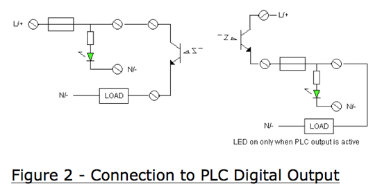 In such a circuit the LED in the fuse terminal and the corresponding LED on the PLC output card should both be on if the fuse is healthy.
When the fuse fails the indicator turns off so there is no indicator current produced in a blown fuse situation. Fuse modules, i.e. a printed circuit board in a DIN rail mounted housing, can include the neutral/0 V connection so fuse healthy indication is easily achieved.
However, most fuse terminals do not include terminations for the neutral/0 V so this type of status indication is less common than blown fuse indication. An exception is Weidmuller’s KDKS1 family.
In the case of blown fuse indication, the LED circuit is located in parallel with the fuse. When the fuse is healthy the voltage drop across the indicator circuit is insufficient to energize the LED. If the fuse blows, the supply voltage is now applied to the indicator circuit and the LED illuminates. As the impedance of the LED circuit is generally much higher than the load, the majority of the supply voltage is applied to the LED circuit. 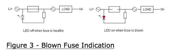
 No terminations for the neutral/0 V are required. The drawback is the LED circuit produces a current flow through the load when the fuse is blown.
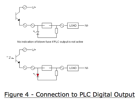
This “leakage current” is undesirable and should be kept to a minimum so that it does not pose a safety hazard. LED currents as high as 2.5 to 3 mA are not uncommon, but at least one DIN rail fuse terminal supplier offers blown fuse indication that draws 0.25 to 0.5 mA and still provides highly visible LEDs.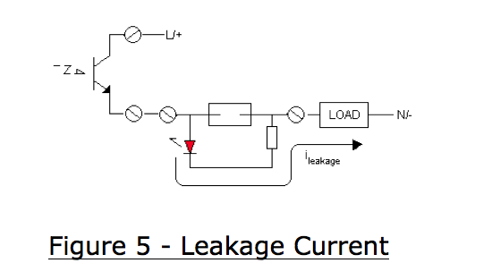 Another drawback with blown fuse indication is that the indicator would only function when the PLC output is energized since that is required to complete the circuit. This means that if both the PLC output LED and the fuse terminal LED are on then the fuse is blown.
If only the PLC output LED is on the fuse is healthy – or the wire between the PLC and fuse terminal is broken – or the load is disconnected. Blown fuse indication is not as definitive as fuse healthy indication.
Emphatec is currently working on two new types of fuse terminals that will address the issues described above. The first will be a 5 x 20 mm fuse terminal that not only provides LED status indication but will also provide a digital output (active when the fuse is blown) that can be used to energize an alarm or a PLC/DCS digital input.
The terminal includes an N/- connection so there is no leakage current. The digital output is at the same voltage level as the supply to the terminal – either 24 Vdc or 120 Vac. This product should be released in the fall of 2012.
The other new development is the “DEPRO – CLSI” – which offers the best of both worlds – no leakage current fuse healthy indication with no need to provide a neutral/0 V connection. This is achieved by installing current sensing in series with the fuse.
If the fuse is powered and healthy and the load is connected (not open circuit) then the indicating LED energizes. Like blown fuse indication the indicator circuit only works when the PLC output is energized. 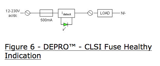 The current sensing circuit must be compact (current transformers would be too large) and introduce minimal voltage drop. Emphatec’s circuit drops the voltage by approximately 0.8 V regardless of the current flow so to keep power dissipation to a minimum the maximum fuse rating is 500 mA. This is more than sufficient for the majority of PLC I/O and control loop applications.
The DEPRO – CLSI is designed for both ac and dc voltages and operates from 12 to 230 V – one fuse module will work in a wide range of applications. The LED intensity is not dependant on the supply voltage but is optimal at a load current of 10mA of higher. At lower load currents it may be difficult to see the LED when illuminated.
The DEPRO – CLSI is 11.2 mm wide and accepts 5 x 20 mm fuses. It is planned to get this product CCSAUS approved for Class 1 Division 2/Zone 2 applications and launch it in late 2012.
————————————-
This article was contributed by Emphatec, with engineering offices in Canada and Asia. It also has a network of sales agents and distributors across North America.
www.emphatec.com