PAM-4 creates new test challenges
By Tami Pippert, Keysight Technologies Inc.
Test & Measurement EngineeringFor five decades, digital electronics has flourished by transmitting 1’s and 0’s using NRZ (non-return to zero) signaling across communication channels. Clever engineering coupled with printed circuit board and semiconductor advances have allowed ever-increasing clock rates. In fact, our industry now has many digital serial standards that run at multiple Gb/s bit rates.
However, the industry is at the cusp of a huge barrier for NRZ signaling speed advances. Higher frequencies attenuate significantly on printed circuit board material narrowing the degree which additional speed advances can be made. The technical determination to achieve higher data rates is driving the emergence of PAM-4 (Pulse Amplitude Modulation) signaling. The change is coming and will make a huge impact on the methods and tools engineers use to debug and test the physical layer of high-speed serial buses.
For NRZ signaling, data bits transmit serially one at a time. At any valid time a signal can be a 1 or a 0 depending on the voltage level, meaning that one bit is encoded per symbol. Figure 1 shows NRZ signaling and the resulting eye diagram. Widely used to determine communication channel quality, eye diagram measurements play a key role in debug and validation of numerous NRZ-based serial standards such as Ethernet, PCIe, USB, SATA, SAS, HDMI, DVI, Thunderbolt, and MIPI. How fast a symbol can change, defined as the baud rate, is equal to the bit rate for NRZ signals. The Nyquist frequency of these signals equals one-half the bit rate, and faster bit rates are achieved by increasing the fundamental Nyquist frequency of the signal.
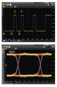
Figure 1: NRZ signals encode a single bit on each symbol and produce the traditional eye diagram from which numerous measurements are made.
PAM-4 signaling
PAM-4 signaling allows 4 possible voltage levels resulting in three stacked eye diagrams as shown in Figure 2. Four unique voltage levels, allow each symbol to represent two bits. Baud rate refers to the number of signal or symbol changes that occur per second. For a given baud rate or fundamental Nyquist frequency, this technique doubles the bit rate versus NRZ signaling. Using the same baud rate, PAM-4 achieves double the throughput. Or, using one-half the baud rate, PAM-4 can achieve the same throughput as NRZ techniques.
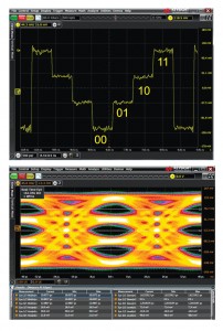
Figure 2: PAM-4 produces twice the throughput versus NRZ signaling when both are using the same baud rate. PAM-4 does this by using four voltage levels and encoding two bits on each symbol. The transitions between crossings produce an eye diagram with three distinct eyes.
Let’s look at a specific example for a comparison. Let’s say we want to build a communication channel that has a throughput or bit rate of 50Gb/s. For an NRZ signal to achieve 50Gb/s, the baud rate is also 50Gb/s bit rate, and the signal’s Nyquist frequency will be 25 GHz. To achieve the same 50Gb/s bit rate using PAM-4 signaling, we have a baud rate of 25Gb/s and a Nyquist frequency of 12.5 GHz. PAM-4 achieves the same 50 Gb/s bit rate at ½ the baud rate as NRZ signaling. Why is this so important?
The move to PAM-4 is technically required for some applications due to high-frequency attenuation in printed circuit board materials. For 400G Ethernet for example, even with advanced board material, the channel loss approaches -40 dB with 56 Gb/s NRZ. For other applications, economics may play a more significant driver in allowing lower-cost printed circuit board material and connectors to be used.
Will NRZ signaling continue to be used for some Gb/s applications? Certainly. Tons of electronic applications currently exist and will exist long into the future where NRZ signaling speeds are sufficient. We’ve seen an increase in NRZ signal speeds from a few MHz in the 1980’s to tens of MHz in the early 1990’s. Equalization techniques, such as de-emphasis on the transmitter side coupled with receiver techniques such as CTLE (continuous time linear equalization) and DFE (decision feedback equalization), have kept NRZ viable for many standards such as PCIe gen 3 technology running at 8Gb/s and USB 3.1 running at 10Gb/s. For bit rates in excess of 10Gb/s, design teams will have high motivation to consider some form of PAM implementation.
One of the likely first large deployments of PAM-4 signaling will be 400G Ethernet. 400G Ethernet will play a key role in faster data centers infrastructure. A common 100G Ethernet implementation is 4 lanes of 25 Gb/s NRZ signaling. For 400G Ethernet, the communication channel requires four times the throughput of 100G. The most likely 400G implementation will be 8 lanes of 25 Gbaud with PAM-4 signaling. The doubling of lanes and use of PAM-4 signaling achieves the required throughput increase of four times relative to 100G Ethernet. As other serial standards look beyond the 20Gb/s NRZ bit rate, we’ll likely see most move to some form of PAM. This could be PAM-3, PAM-4 or some other PAM-n implementation.
PAM-4 presents a host of new measurement challenges. SNR (signal noise ratio) is lower as there are now three eyes for the same vertical range that a single NRZ populated. This makes low-noise imperative for measurement equipment. Test equipment has not previously needed to determine multiple threshold levels for eye diagrams. Due to different rise and fall times between crossings, ISI (inter-symbol interference) can be more significant. Eyes can be skewed relative to each other. Eye heights may not be symmetrical resulting in amplitude compression of one or more of the eyes. Equalization applications running on oscilloscopes and BERTs were designed for NRZ signaling.
Receiver testing
PAM-4 brings a myriad of new measurement challenges for both receiver and transmitter testing. For receiver testing, a BERT (bit error rate tester) has been the go-to instrument for testing physical layer Gb/s serial standards. BERTs provide both pattern generation and error detection to measure bit error rates, and also allow for jitter injection to stress the eye. The challenge with traditional BERTs is that the technology is customized for NRZ signaling. BERTs don’t naturally have the ability to provide multi-level pattern generation. A user could combine two BERT NRZ channels to create one PAM-4 channel by attenuating one of the channels by 6dB, but this method is much too complex and much too expensive for most users. As well, it does not technically provide the required multi-level stress testing for PAM-4 eyes.
For PAM-4 receiver testing, a high-speed AWG (arbitrary waveform generator) has become a better alternative. The AWG’s arbitrary nature allows it to generate any PAM-4 stress type. This flexibility makes it a great tool for standards that are evolving, or testing methods that haven’t yet been determined. In additional to PAM-4, an AWG is also capable of providing receiver testing for PAM-3, PAM-5 or any other future PAM-n scheme. An example of an AWG for receiver stress testing is shown in Figure 3.
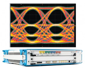
Figure 3: PAM-4 receivers need to be sensitive to additional artifacts beyond traditional jitter types found in NRZ signaling. PAM-4 eyes may be skewed one from another in the time domain. Or from a voltage perspective, there may be non-linear vertical behavior producing amplitude compression as shown. High-speed arbitrary waveform generators like the 65 Gsa/s Keysight M8195A enable the required PAM-4 receiver stress tests.
Transmitter testing
Giga-bit NRZ serial standards have long used oscilloscopes for transmitter testing. Oscilloscope manufacturers have developed PAM-4 analysis applications that can run on sampling scopes, often referred to as DCAs (Digital Communication Analyzers), and real-time oscilloscopes. These PAM-4 applications enable the instruments to unfold and measure PAM-4 eyes as shown in Figure 4 below. This allows the scopes to be used for PAM-4 transmitter testing.
PAM-4 signals have a lower signal- to-noise ratio than NRZ signals. This makes it imperative that the tools used have low noise. DCAs offer the lowest noise, lowest jitter and lowest price/bandwidth for PAM-4 testing. These attributes make them well suited for PAM-4 measurements. DCAs require an external trigger which, for some PAM-4 systems, is more limiting than using a real-time oscilloscope that doesn’t require an external trigger. Real-time scopes also have an advantage of being able to display eye diagrams that are closed or have other impairments allowing for additional PAM-4 debug. Both types of scopes with PAM-4 application report eye height and width measurement for each of the three PAM-4 eyes.
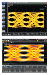
Figure 4: For PAM-4 transmitter testing, an optional application running on scopes enable eye diagrams and analysis. A PAM-4 eye diagram from Keysight’s DCA is shown on the left while a 63 GHz Infiniium real-time scopes example is shown on the right. The oscilloscope’s PAM-4 application automatically recovers the embedded clock, performs automated or user-defined vertical slicing, and performs automated eye height and width measurements.
For users who are considering PAM-4 signaling, a number of webinars and papers are available on the Internet. A quick web search on ‘PAM-4’ will also reveal several informative white papers on the topic. Consulting with a test and measurement supplier well in advance of the need will help your team determine equipment and software application needs and budget requirements. Engaging your measurement suppliers will also enable your team to determine how well each vendor meets your need for transmitter and receiver testing.