Designing sensor-based IoT devices with coin cell batteries
By Steven Keeping, contributing writer for Avnet Electronics Marketing
Power Supply / Management EngineeringA popular vision of the Internet of Things (IoT) is that it will comprise billions of sensors gathering information about their local environment and transmitting that data back to servers in the cloud. Such data will be compiled, analyzed and shared by server-based applications that will use it to do everything from controlling irrigation and managing traffic congestion, to monitoring diabetics’ blood sugar levels and automatically re-ordering stock when store shelves run low.
Turning this vision into reality requires engineers to design a new generation of sensors that are unobtrusive, low maintenance and inexpensive. Devices that are compact and lightweight, with relatively simple circuitry and wireless connectivity fit the bill. While energy-harvesting techniques are continually improving, constantly active IoT sensors will probably demand the more reliable resources of a battery. However, constraints on the size and weight of such sensors restrict the size of the power source, in turn limiting the battery’s capacity. And just to make the designer’s challenge a little harder still, sensors in the IoT will require long battery life to keep maintenance manageable.
Enter the coin cell battery
Designers of mobile products are experienced in coming up with circuits that work efficiently and in choosing power-frugal components to ensure long battery life. But engineering tiny, battery-powered wireless sensors is an altogether tougher challenge.
However, designers can call on the experience of original equipment manufacturers (OEMs) that have fabricated compact wearable sensors, such as heart rate monitors (HRMs), that use wireless technology to send information to a sports watch. These products employ many of the technologies that will be needed for ubiquitous IoT sensors. The CR2032 coin cell battery (using lithium/manganese dioxide — Li/MnO2 — chemistry), which initially came to prominence as a common choice for electronic watches, is the popular choice for powering these wearable sensors. Manufacturers of the prevalent CR2032 coin cell battery include Duracell, Eagle Picher, Energizer, Maxell, Panasonic, Philips, Rayovac and Vinnic, among others.
Panasonic’s version of this battery, which is typical of the type, offers a nominal voltage of 3V and nominal capacity of 225mAh before the battery is exhausted. Panasonic advises a maximum continuous load of 0.2mA from this battery. Research by others shows that the maximum transient current draw for a CR2032 coin cell is about 40mA if the battery is not to be seriously compromised. While the nominal capacity provides a guide regarding the life of a CR2032 coin cell in a wireless sensor, there are many influences on how the battery will actually perform in practice. For example, a nominal capacity of 225mAh for a device drawing a continuous load of 0.2mA will provide 2V or greater for approximately 47-days. But few products would exhibit this performance in the field.
There are three key factors that ultimately determine usable (as opposed to nominal) capacity of a coin cell:
• The operating temperature
• The battery load
• The “functional endpoint” (FEP) of the circuitry
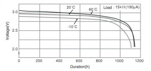
Figure 2 illustrates the effect of temperature on the performance of a Panasonic CR2032 coin cell battery under a load of 0.19mA. The graph shows that the effect of high temperature (60 C) isn’t overly dramatic, but lower temperatures do have a more significant impact that could come into play if wireless sensors are employed outside.
The FEP is determined by the component with the highest voltage requirement in the design. Modern silicon is economical, but there may be a chip, for example, that requires at least 2.2V in order to function. Even if the rest of the components can operate from a lower voltage, if the 2.2V device is critical to the operation of the sensor, the product will be useless once the voltage falls below this threshold.
One option is to swap the voltage regulator from a linear converter to a switching type (which can boost a battery’s voltage), but this adds cost and complexity to the design and may be hard to justify for a compact sensor. Figure 2 demonstrates it can be seen that, over a wide range of temperatures, the difference in lifetime for a product with an FEP of 2.2 V isn’t very much when compared to that of an FEP of 2 V; but under different operating conditions the effect can become much more significant.
For example, a wireless sensor typically employs a low-power radio technology, such as Bluetooth Low Energy or ZigBee. Such technology keeps the average power consumption down by engaging an extreme duty cycle whereby the radio is asleep for most of the time. However, when operating, the radio places a relatively high demand on the battery. Because the radio switches on and off in a regular sequence, the demand comes in pulses, which have a more detrimental effect on battery lifetime than a constant load.
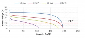
Figure 3 shows discharge curves for a CR2032 coin cell battery (for a device with a nominal capacity of 225mAh) when subjected the 10, 30, 50 and 80mA high-peak, pulsed currents under a cycle comprising a 1-ms burst of activity at a frequency of 40Hz. At 80mA, it can be seen that both the high-peak current and the high-average current challenge the battery and will likely cause damage. At more practical operating currents of 30 and 10mA, the 2V FEP is reached after the battery has been drained of 180mAh and 190mAh, respectively. Note that at an FEP of 2.2 V, the difference is more marked. At a pulse current of 30mA, the 2.2V FEP is reached after just 160mAh compared with 185mAh for a pulse current of 10mA.
Maximizing coin cell battery life
When formulating a design for a wireless sensor, a good place to start is the datasheet for the radio chip because that component exhibits one of the largest power draws in such a device. It’s advisable to check both average and peak-current for applications similar to the target use case.
Beyond the radio chip, the engineer should consider extending the FEP margin by selecting chips with as low a minimum supply voltage as possible and minimizing the current drain by selecting devices with the lowest peak current. To keep the design simple and reduce the bill of materials (BOM), the designer should select a linear voltage regulator, but take into account that this type of regulator can only step down the input voltage to a lower output voltage — and the higher the difference between input and output, the lower the efficiency of the regulation and the greater the impact on the battery.
By incorporating a power management system that prevents multiple high-drain devices loading the battery at the same time, the coin cell’s life can be further extended. Design engineers should remember that any high-peak, pulsed load — not only those from RF circuitry — will similarly impact battery life. For example, the high-peak, pulsed loads could also come from a combination of LEDs, vibrating motors, piezoelectric buzzers, LCD backlights and other components.
Dividing the ‘corrected’ battery capacity (an estimate of the useable capacity for the particular application before the FEP is reached and is likely to differ from the nominal capacity) by the average current draw in the typical operational mode will provide a good estimate of battery life for the product in the field.
————————-
Source: Original article published in Avnet’s Internet of Things portal.